Dual Digital Sound Design Ins&Outs Control Voltages Bounching Switches Debouncing Switches Manual Noise Source EPROM configuration 64k conversion Samplerate Preparing Samples Sounds Sequencer Inputs MIDI to Trigger Battery CPU Board Potentiometers Bus Board Faults Faults II EPROM modification
At its core SDS 7 is a multitimbral hybrid synth with 4 sound sources for each voice, optimized with detuning capabilities for drum sounds.
In the mid 80’s it was usually sold as a 5 piece drum kit, bass, snare, 3x toms (4365US$ ) with the option to add a single cymbal bundle (496US$). A single voice cards was listed at 310US$.
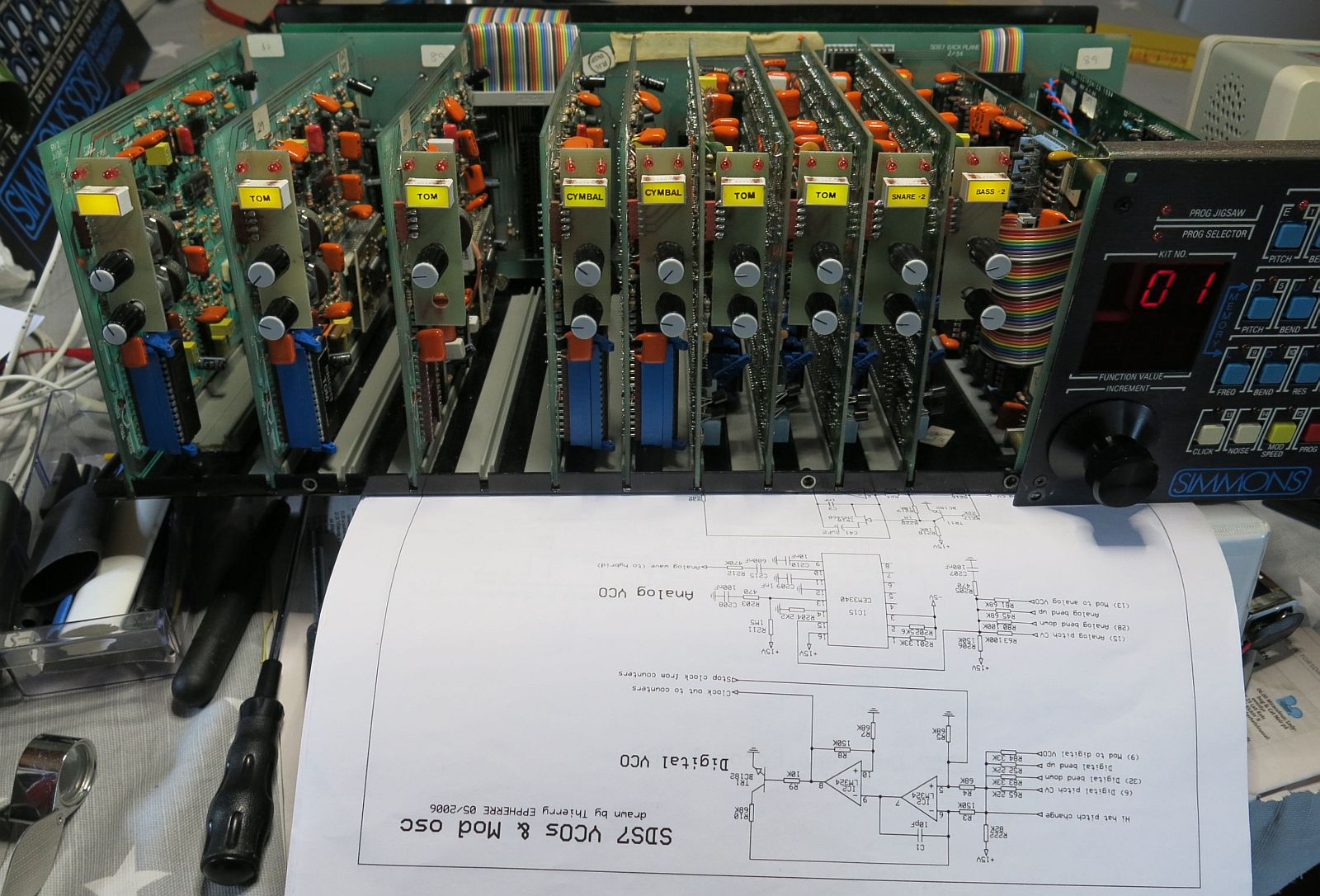
Maxed out it can hold 12 voice cards, - or modules as they’re called. But Simmons also refer to the SDS 7 brain as module, so not to confuse we call them voice boards (or cards) throughout. SDS 7 standard voice boads are referred to as Analog/Digital, to different them from Dual Digital card that came later.
Hot for its time
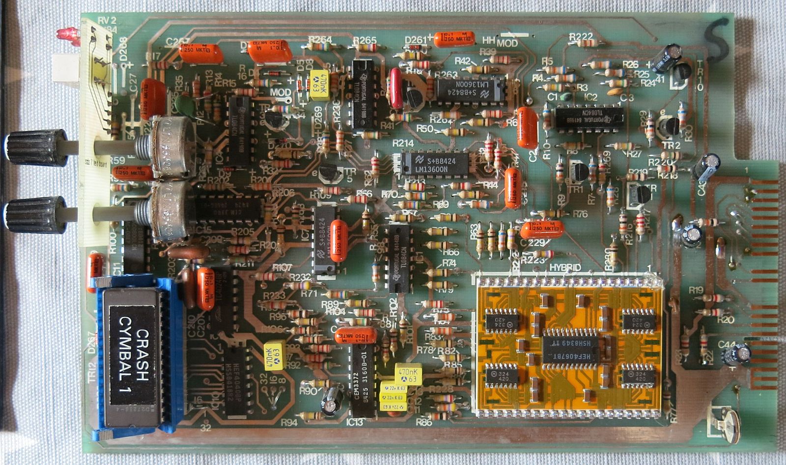
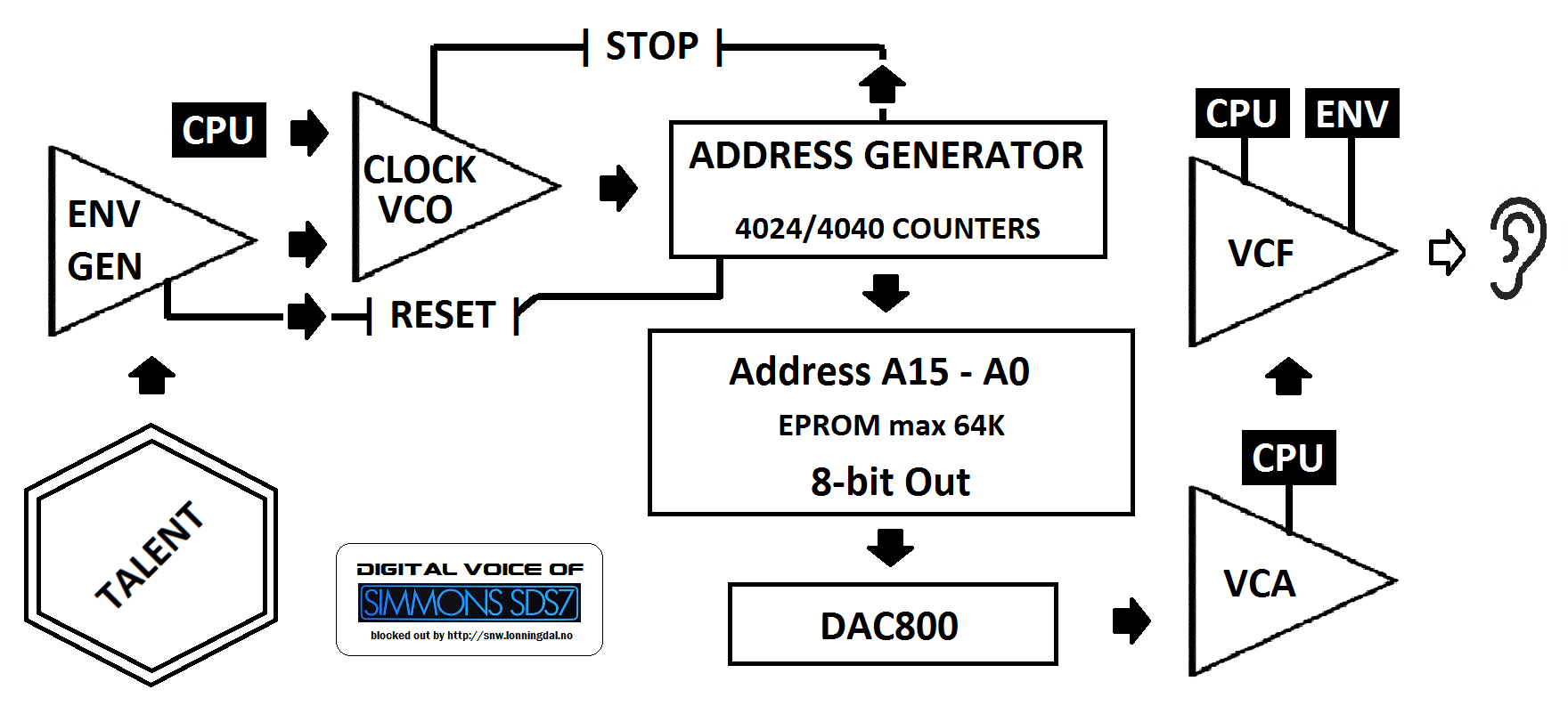
— are the 8-bit 8-32KB EPROM sample player implemented with DAC0800 going into an analog 4-pole lowpass filter from Curtis, the legendary CEM3372 ‘synth on a chip’. Several synth manufactures depended on this chip at the time, among them the incredible Matrix 12 by Oberheim. SDS 7 also make use of this chip's 2 controllable mixer inputs and VCA circuit.
— the ability to store presets
Hot for some of us in this digital age
— are the analog oscillator build on CEM3340, sharing the same CEM3372 filter. It can do frequency sweeps from 20 to 6000Hz. Only triangle waveform is utilized.
Other popular and well reputed synths using this oscillator chip are Roland SH-101, Jupiter 6, Memorymoog, OB-Xa, Prophet 5r3.
To complete each invidual voice board
- click generator
- envelope generator
- LFO
- 3 pitch up generators
SDS (Simmons Drum Synthesizer)
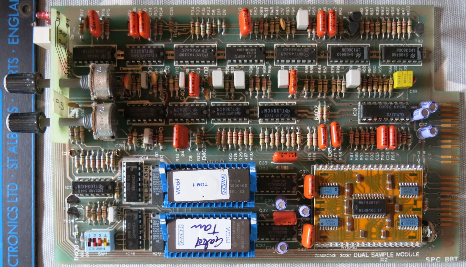
Later Simmons introduced a new voice card for SDS 7 where they replaced the analog oscillator with yet an 8-bit EPROM player, still using the 24dB analog Curtis filter.
”A new generation of modules has been produced to further increase the versatility of the SDS 7. In these modules, the analog section has been replaced with a second digital section, there are separate envelopes for each digital sound as well as a third for the noise generator.The second sample has a programmable threshold control which allows for second sample to sound at a pre-determined dynamic from the pad, and the click circuit has been re-designed to accent the start of the digital sound, I.E. The ‘click’ part of a bass drum. So for the first time the two distinct parts of a sampled drum sound are controllable. Combined with the filter controls and separate ‘bend’ controls for each sample. This module is the most versatile yet, and places Simmons once again at the fore of multi sample synthesis for percussion.”
“Primarily designed to offer the SDS 7 owner the flexibility of the multi sampled approach for the SDS 9 bass and snare drum, the modules can of course be used for any sampled sounds.”
Simmons SDS 7 Dual Sample Module Manual
Looking at each SDS 7 voice card thinking it actually is a complete mono synth is not wrong. Except for housing and power supply only thing they share are, a common noise source and CPU/memory from where they receive 15 control voltages.
Don't think any dedicated drum sound sources from mid 80's could match this number of sound sculpting parameters. Nor do I know of any modern drum module with analog oscillator that can today. Beside less controls for envelopes each voice board match many synthesizers of it's day. A fully loaded SDS7 will store a whopping 180 voice parameter in total for each drum kit.
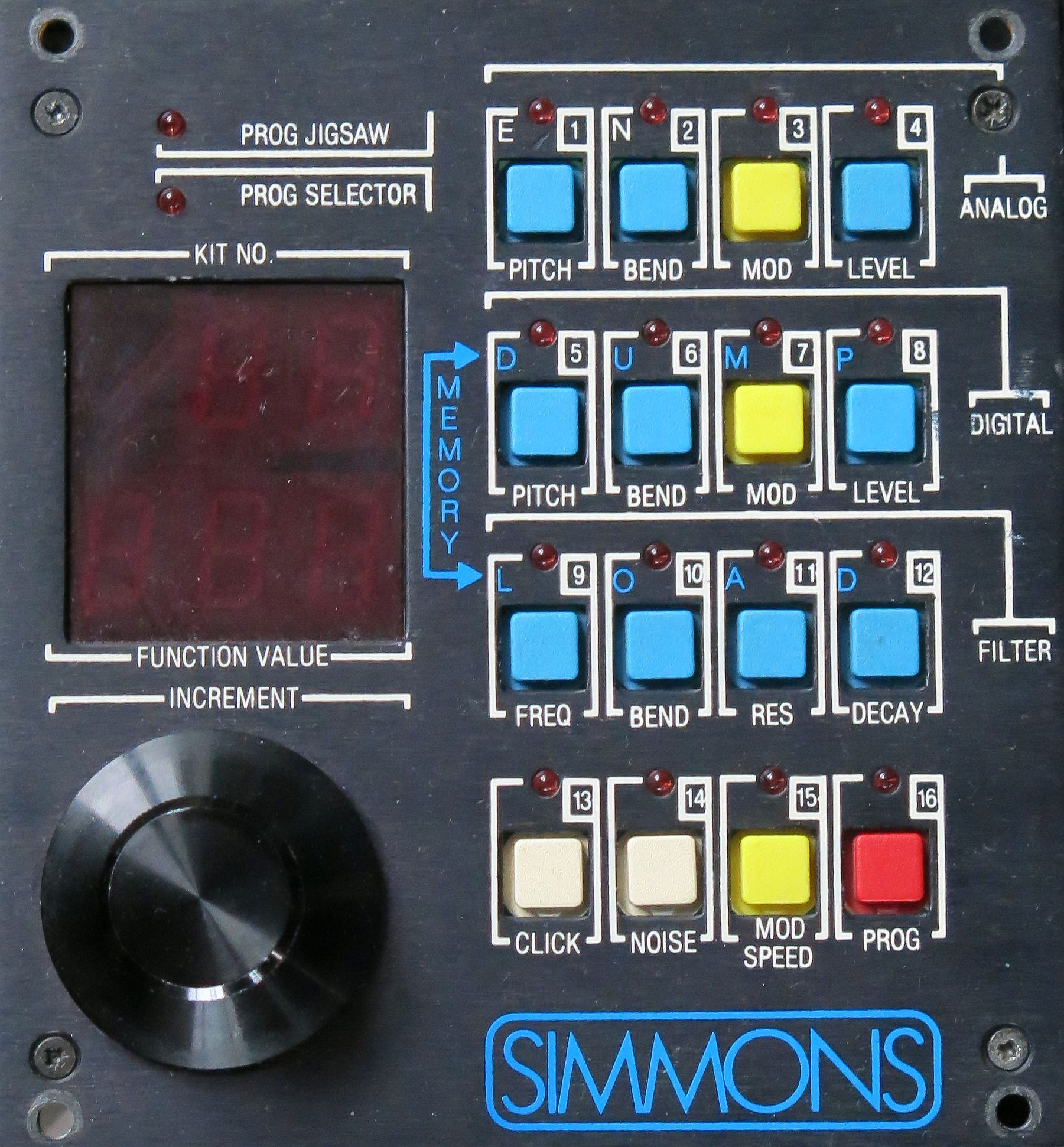
For sound design here are the parameters available to us:
| Analog/Digital card | Dual Digital card |
|---|---|
| Analog Pitch (20Hz-6kHz) | Sample 1 Pitch (VCO 800Hz-44kHz) |
| Analog Bend Up/Down | Sample 1 Bend Down |
| Analog Modulation | Sample 1 Envelope Decay (8-600ms) |
| Analog Level | Sample 1 Levels |
| Digital Pitch | Sample 2 Pitch |
| Digital Bend Up/Down | Sample 2 Bend Down |
| Digital Modulation | Sample 2 Envelope Decay (8-600ms) |
| Digital Level | Sample 2 Level |
| Filter Frequency (100Hz-15kHz) | Filter Frequency |
| Filter Bend | Filter Bend/Sweep |
| Filter Resonance | Filter Resonance |
| Envelope Decay | Sample 1/2 Treshold |
| Click Level | Click Level |
| Noise Level | Noise Level |
| Modulation Speed (0-140 fast range / 140-255 slow range) | Noise Decay (22-600ms) |
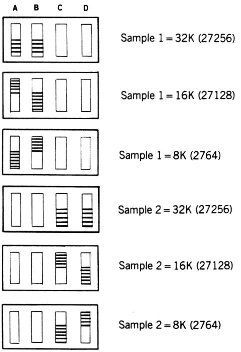
| EPROM switch chart |
”The dual sample modules are programmed in exactly the same way as the digital/analog modules, but note that there is no modulation or bend up as in the analog/digital modules. Bend up is values from 0 to 140, bend down from 140 to 250. The dual digital modules only have bend down from 0 to 250.”
Simmons SDS 7 Dual Sample Module Manual
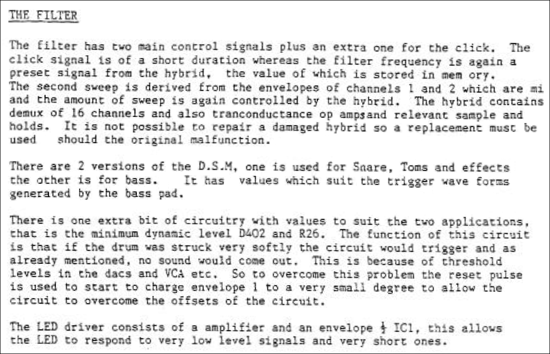
"There are 2 versions of the D.S.M., one is used for Snare, Toms and effects the other is for bass. It has values which suit the trigger wave forms generated by the bass pad."
"There is one extra bit of circuity with values to suit the two applications, that is the minimum dynamic level D402 and R26." more…
Simmons SDS 7 Dual Sample Module Service Manual
Service manual also different what they call Anti splat length to approx. 96ms for bass and 35ms for snare.

User Manual Download all
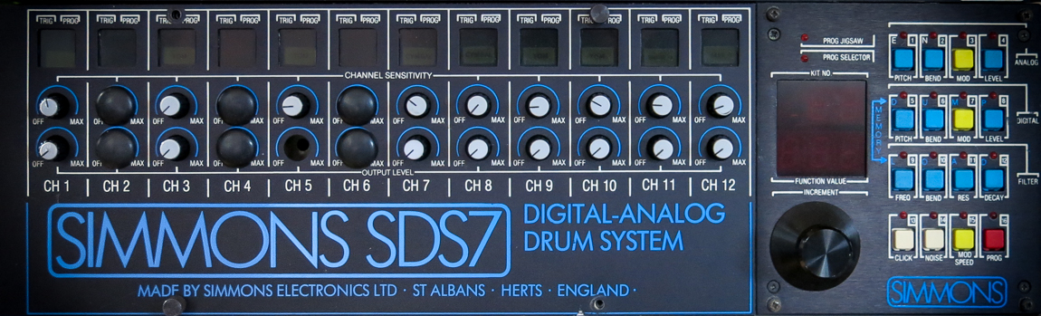
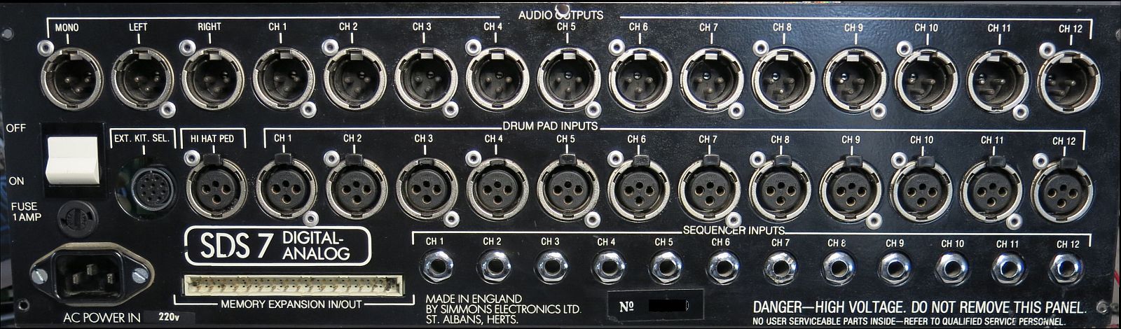
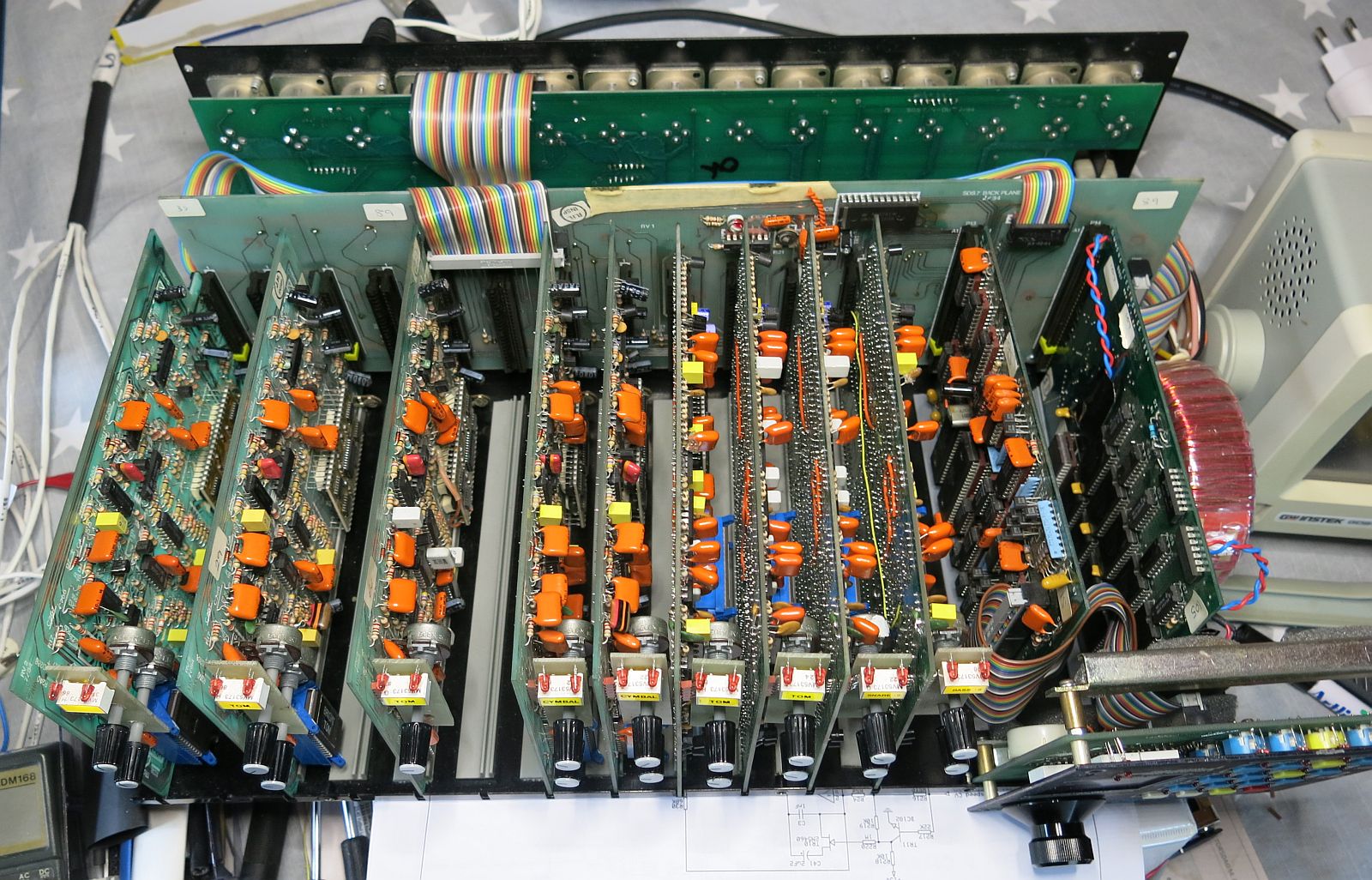
Ins&Outs - most impressive back panel in the industy, with all its unwieldy connectors
Each voice board have two separate trigger inputs. Notice how the sequencer input also support dynamics, a big part of what made Simmons drum voices so unique at its time were due to how they implemented electronics to utelize dynamics to alter the sound. Although some think of Simmons as lack of dynamics and peeew sounds.
Sequencer Trigger Input 0.2Volt - 15Volt Max trigger occurs at approx 10Volt. 2ms positive pulse is needed for safe triggering. Note this input accept gate signal, opening up for even more creative possibilities than the usual drum machine trigger input.
Pad Trigger Input 30mVolt - 500mV Max trigger occurs at approx 450mVolt. Adjustable from front panel. Pin 2 hot on XRL. Pin 1 to ground. Pin 3 (center) not connected. Pin 2 are clamped to ground with a 10k resistor (DIL pack on the back plane).
If your trigger signal is to hot you can lower it with something ironically called a pad, original SDS 7 drum pads use a 1k resistor in parallel with the piezo element. But we are free to experiment, and no piezo is identical. I used to hang a potentiometer on the outside of my snare to be able to connect to different drum modules. My Dynacord P20 bass drum I moded with a switch that had several different caps in parall with the piezo. I used this switch to adjust sensitivety to avoid double triggers. It is not critical where this pad is mounted. You can mount it inside your pads, cable connectors, stomp boxes or inside your drum brain. At one moment in time I had several multi cables made with different resistors in the connectors. Even for audio direct out to meet different requirement from sound engineers/band mixers. Actually when gigging with my Percutter I estimated I’ve spent the same amount of money on cables as I did on electronics.
Individual audio outputs are feed directly from each voice card trough a resistor pad, output is rather low level at 0.6V p/p into 1k load Left+Right/Mono feed 2V p/p into 1k load.
Despite all the heavy XRL connectors on the back sadly none of them are running balanced signals. Pin 2 Hot, 1&3 Ground. For older units with serial number below 250 pin 3 is hot, - vintage style.
Each voice board sends individual out and stereo out on three separate pins. Sadly SDS 7 does not have bus switching features, meaning individual connected channels still remains on the Stereo/Mono bus. When these buses are used as monitor channels it make sense. Not so much in studio where you could benefit from grouping your toms.
To add to this issue Stereo/Mono buses are out of phase with the individual outputs. Mono out is summed from the stereo out over two resistors, after the inverted stereo bus amplification.
All outputs have 3k9 serie resistor with a 4k7 to ground, — later are mounted inside 9 pin SIL packages's.
Hi-Hat Pedal - Do not connect anything other than original Simmons hi-hat pedal to this input, unless you know what you are doing. Now with the warning out of the way lets lessen the drama. What’s special with this input is that it feed 15 Volt on pin 3, ground on pin 1 and on pin 2 it expect high/low return voltages from the H21A1 optical interrupt switch found inside the original Simmons pedal. You will also need one or more hi-hat enabled voice card to make this input useful. Detailed description (in German) on the hi-hat pedal and how to modify your Analog/Digital voice card to receive hi-hat input can be found at: http://www.drummachines.de/beatboxer/stories/sds7hi.htm
 EXT.KIT.SEL. - External Kit Selector where an annoyingly designed option to select 16 of your favorite drum kit. This expensive (287$), big and heavy steel box where filled with St. Albans finest air. Full of nothing it had a thin rubber layer on top with 16 blade switches underneath. For me it was the first thing to find its way into the closet back in the ’80.
Only 8 of the 10 pins are used in this connector, pins are connected as standard 4x4 switch matrix [1-4] x [5-8]. My readings suggest there are some inconsistency as to what kit number come up when pressing different switch combinations. Being under firmware control might explain this. Port is interfaced with 5V logic trough 74S09 and 7407 chips on the CPU board.
EXT.KIT.SEL. - External Kit Selector where an annoyingly designed option to select 16 of your favorite drum kit. This expensive (287$), big and heavy steel box where filled with St. Albans finest air. Full of nothing it had a thin rubber layer on top with 16 blade switches underneath. For me it was the first thing to find its way into the closet back in the ’80.
Only 8 of the 10 pins are used in this connector, pins are connected as standard 4x4 switch matrix [1-4] x [5-8]. My readings suggest there are some inconsistency as to what kit number come up when pressing different switch combinations. Being under firmware control might explain this. Port is interfaced with 5V logic trough 74S09 and 7407 chips on the CPU board.
If XRL connector board on the back need servicing there are some 27 pop rivets that need to be drilled out. Sequencer inputs and memory slot share PCB with the power supply. Luckily there are no active parts for trigger in, nor analog outputs on either of these boards. Note SDS 7 will not boot up if the ribbon cable interconnecting bus-board with the memory cartridge is disconnected.I believe this is due to a reset circuit in conjunction with the power supply use the same cable.

15 Control Voltages
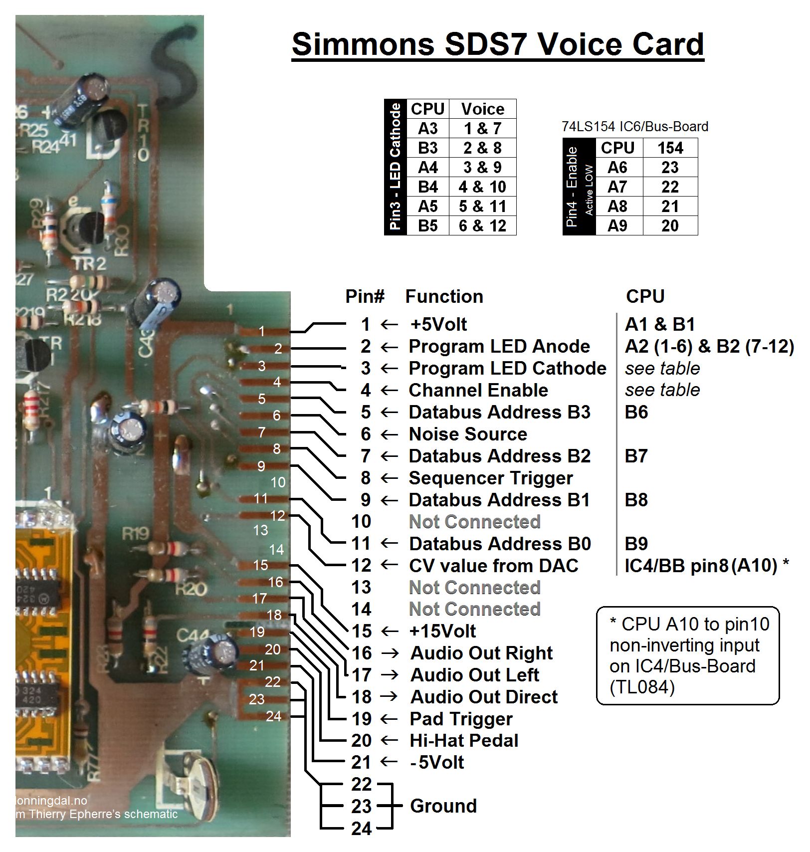
If you’re looking at the voice card wondering where all those 15 CV signals connects to, they actually share one common CV line on pin 12.
Address for the local multiplexer on each voice card are received on pin 5, 7, 9 and 11.
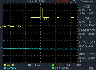
For each CV value CPU toggle pin 4 LOW for the receiving voice card through IC6/Bus-Board (74LS154). Independent if there is a card in the slot or not CPU board will burst out all 15 CV values to each of the 12 slots continues at speed around 7.3kHz, or every 7.3 millisecond if you prefer.
CV value in the range of 0-255 are read from the memory board in same order as layout on the panel and decoded in the central 8-bit DAC IC4/CPU board Ferranti ZN428E. Then send to pin10 non-inverting input on IC4/Bus-Board (TL084), from this op-amp output pin8 it comes as control voltage in the range 0-2.5V on bus pin 12.
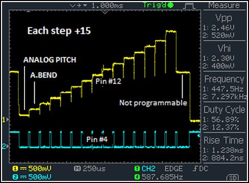
Starting at decimal 15 each step here increases by +15. The 16. (or 1.) value seems to be a calibration value set at half the max CV voltage, here at 1.23V. It is not user programmable. Notice how pin 4 is held low for the duration of this step also.
With 16 controls (incl the empty one) on each of the 12 voice card the CPU board are updating every sample and hold circuit on the voice boards approxly 38 times a second.
On my unit master CV max at 2.46V, meaning each of the 256 CV controller steps differ by 9.61mVolt.
Noise Source
Located on the bus board between the Stereo Bus Summing Amp and the 4-Line to 16-Line Decoders we find the noise source common for all the voice boards on pin 6.
Digital voice - EPROM configuration
SDS 7 will play any EPROM you can fit in the 28pin socket. That is not to say it will play the sound correctly, although it might sound interestingly. To do so you need to tell the sample engine what size EPROM is inserted by solder two wire jumpers on the Analog Digital board.
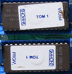
Officially SDS 7 where released with 'locked' eprom sizes. Bass and Snare 8k, Toms 16k and Cymbals 32k (early boards have 2x16k).
For Dual Digital cards Simmons corrected their fault implementing dip switches, making it possible to sell the consumer single sounds at 76$ a pop, thats less than 1 second worth of noise.
| Name=bit size [k] | Bytes | Samples | Address range 0 - |
|---|---|---|---|
| 27C64 | 8k | 8192 | 01FFFh |
| 27C128 | 16k | 16384 | 03FFFh |
| 27C256 | 32k | 32768 | 07FFFh |
| 27C512 | 64k | 65536 | 0FFFFh |
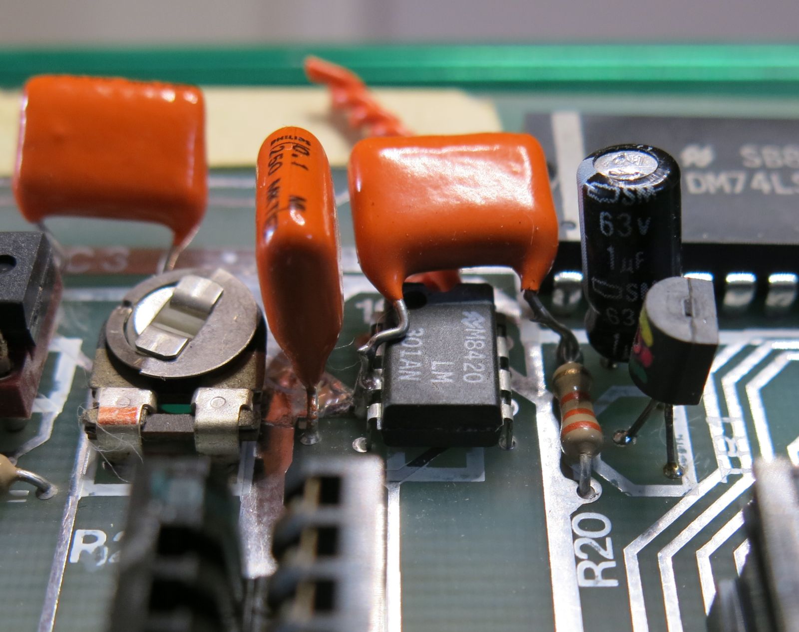
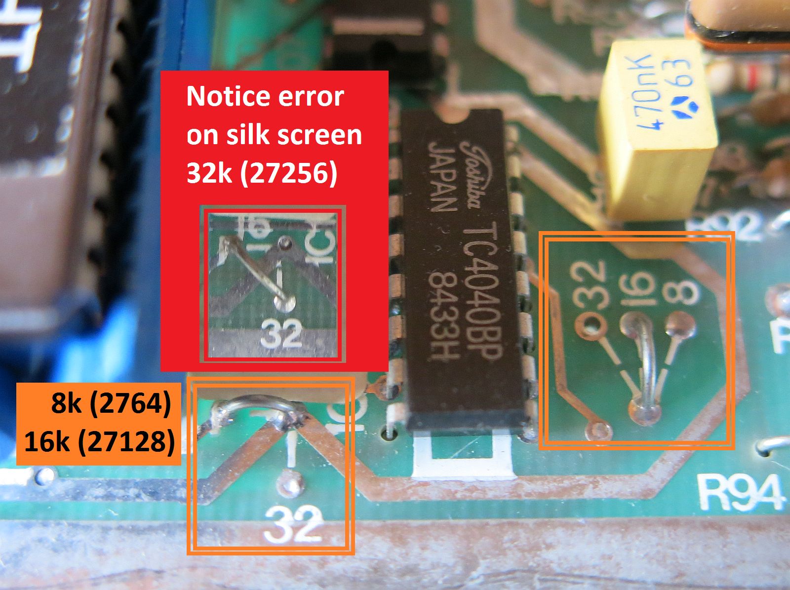
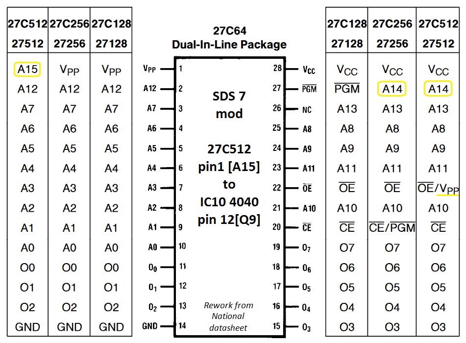
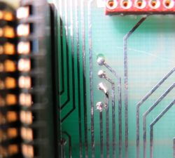
Wire jumper closest to the EPROM socket hold pin 27 on the EPROM at 5V to ensure that EPROM type 2764 and 27128 doesn’t activate program mode. For 27256 (and 27512) pin 27 function as address A14, wire jumper connects this pin to pin 13 (Q8) on binary counter IC10 (CD4040). Silk screen on pcb is confusing doe to an error, please see picture below for correction.
Wire jumper furthest away from the EPROM ensures the sample player stop after one complete sample has played. Signal is tappet from IC10 (CD4040) pin4 (Q7) 2764, pin13 (Q8) 27128, pin12 (Q9) 27256 (for your 27512 modification pin14 (Q10), wire jumper then connects anode side of D267 before going to the clock generator.
SDS 7 do not care if you use 27 series or 27C EPROMs. When buying go with 27C as it is more likely to play well with your cheap programmer. Reason is the old 27 series generally need much higher program voltage (21-25V) than its modern 27C counterparts (12.7V).
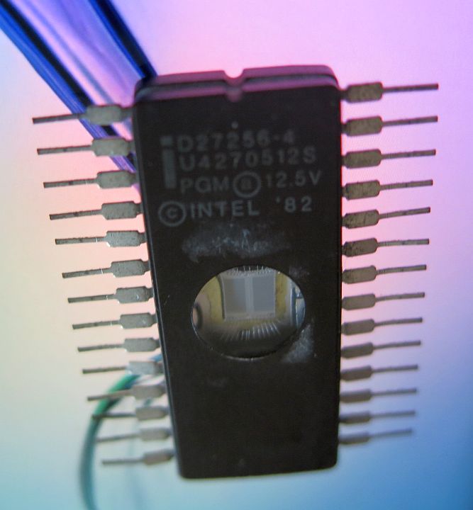
To confirm this general rule this picture show an exception labeled D27256 with program voltage 12.5V.
Digital voice - 64k conversion
Simmons voice cards where from a time 27512 EPROM must have been few and scarce, if even availably. Today their cost is similar to 27256, but maybe more interestingly we can find them as eEPROM saving us the tedious UV light erasing of normal EPROMs.
In Michael’s great article on how to convert our Analog/Digital board to hi-hat he also show how to modify the card to accept 27512 EPROM. Google translation from German has a lot to be desired so I ended up reading datasheets to understand what’s going on. Two short wires is all it takes:
27C512 pin1 [A15] to IC10 (CD4040) pin 12[Q9], this enables one more address pin thereby doubling max sample capacity. IC10 (CD4040) pin 14[Q10] to wire jumper furthest away from the EPROM. Think of it as fourth option for 4k, 16k, 32k, and now 64k, or solder directly to anode side of D267 and remove this wire strap as Michael demonstrate in his article. This pin enables correct stop position for the counters, letting the sample play to the end.
Intrusive Noise
Early SDS 7 are infamous for its high noise floor. On my first SDS 7 in the ’80 mono/stereo outputs were practically useless due to high clock noise. Simmons tried to fix this with Noise Canceling which actually are very efficient. Older units can be modified similar way as Simmons did.
I did an observation while doing finishing tests on my SDS 7. Mono and Stereo out still have some digital clock noise. This noise is not possible to adjust with the noise cancellation VR on the buss board. While testing if the noise where coming from a defective voice card I noticed the noise are actually coming from empty slots. While direct out for slots with voice card inserted have normal hiss, noise signature are identical for all three direct out without voice card inserted as noise summed and amplified on the mono/stereo bus.
This is somewhat surprising as every direct out are terminated to ground with a 100k resistor on the bus board and a series resistor on the connector board. As far as my notes show stereo out from voice cards comes from the 4k7 pan pot (center tap to ground) over two 820ohm series resistors located on the voice card (R19/R20) function as mixer resistors for the stereo bus. Without card inserted there are no summing resistors connected and the PCB traces for the stereo bus are floating.
I’m clearing my work bench for another project at the moment, this issue are going in the pile of 'things to do'.
Bouncing Switches
I decided to remove a cap to take measurement of a tactile switch to search for replacement. To my surprise I found they can be taken apart and cleaned. Now be warned. I didn’t know this and spend best part of the day on the floor searching for the all the small part inside the cap that I dropped.

Inside the cap there is a spring plate, a contact disk and a tiny spring. Contact plate and contact surface soldered to the pcb have a thin contact coating of some kind. If studied under a magnifying glass one can see this alloy is worn with blank spots where contact points meet.
Using my preferred method I applied Deoxid to both the disk and switch surface and let it soak for 10 minutes. Just to find out Deoxit will dissolve the alloy used in these switches.
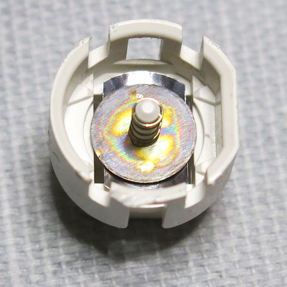
For the rest of the switches I used Lotoxane cleaner. Inside of the plastic caps and plastic part mounted to pcb where also cleaned.
To make sure the switch doesn’t land on the same contact points I very gentle squeezed the long sides of spring plate between my fingers. When writing this I'm thinking I rather should have taken apart more switches and mixed parts between them in attempt to accomplish this.
Big improvement in performance. Too early to tell if it will last long enough compared to invested time doing this fiddly job.
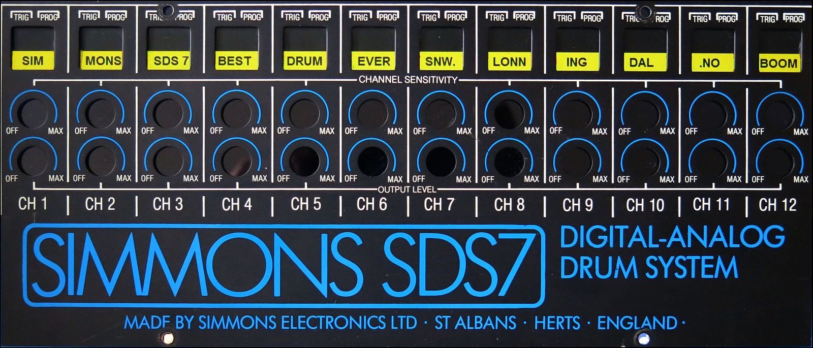
LED on the Voice Cards
Often seen in adds for second hand SDS 7 voice cards are reference to LED’s as a way to tell if the voce card are in working condition. But can this be done safely? Short answer is ‘NO!’
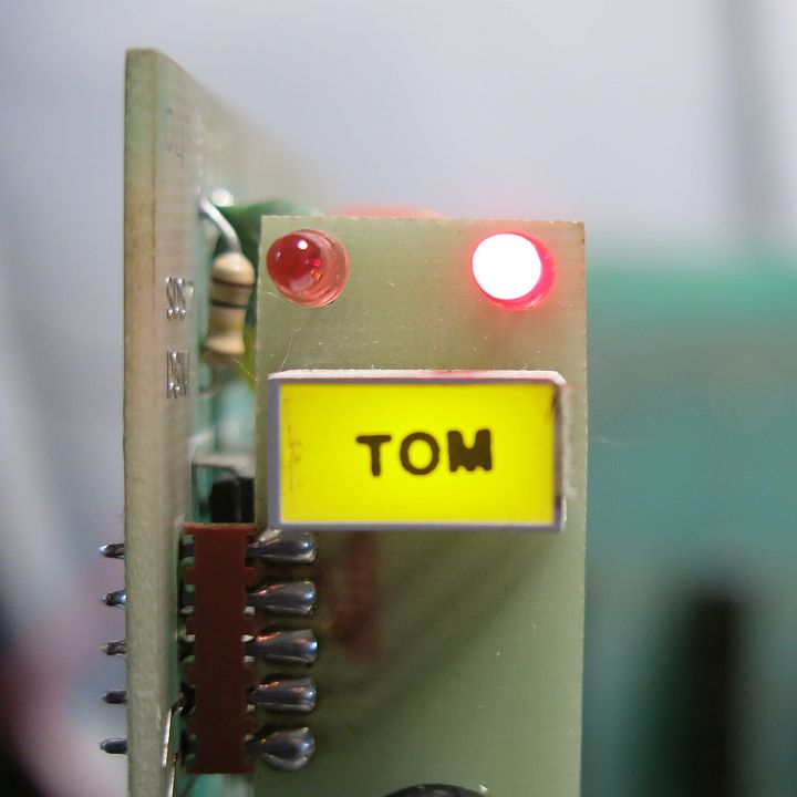
Prog (Program) is used to indicate that CPU will allocate all voice parameter adjusted on the control panel to the memory location representing the slot number where Prog LED is lid up. Both cathode and anode have dedicated pins on the voice card going to a 7407 LED driver on CPU board. Meaning this LED can’t tell anything about condition of your voice card. It can however tell if some parts of the CPU board is functional if you can turn the wheel and select any of your installed voice cards.
Trig (Trigger). Although giving a good indication if the card is been triggering the name is somewhat misleading. This LED is driven by the envelope circuit on the voice card. Value of Decay parameter should change how long this LED is illuminated when the envelope is triggered.
Yellow Backlight. I got one not lightning up, I’ll come back when I figured this one out. I suspect it just goes to the +5V power line through a resistor.
Turned out to be a contact problem for the 5V power line on the edge connector. When board are powered you can measure 4.6 to 4.8V from center pin and the pin above it on the header connector for the LED PCB.
Digital voice - Sample rate
I wanted to better understand the relationship between sample rate and pitch settings on my SDS 7. Table below show measured clock speed going to the sample engine in relation to pitch setting on panel.
I wasn't quite able to reach 44100Hz, adjusting value of R222 could fix that if needed.
| Display value | Clock speed |
|---|---|
| 48 | 0.8k* |
| 71 | 8k |
| 81 | 11k |
| 97 | 16k |
| 118 | 22k |
| 158 | 32k |
| 255 | 43.4k |
* This is the slowest oscillation I was able to measure with my gear. Oscillation seems to stop at display value 50 (+/-3).
Please understand all values are approximations as it is impossible to lock the clock speed too exact sample rate with only 8-bit control voltage resolution and no calibration for referance voltage for the clock oscillator. Also the speed vary a lot. The are two reasons for this, first when the clock oscilator ramp up and second the Bend function is never completely off. Last could probebly be fixed with a trimmer for R65, but I think it would be tricky to calibrate and probably not stable.
Digital voice - Preparing samples
For Windows 10 users Audacity 2.1.0 http://audacity.sourceforge.net/ seems to have the conversion tools needed.
To convert audio file to .bin compatible file for the EPROM programmer select File > Export Audio from the files dialog select Other uncompressed files, then press the button Options. Set Header: RAW (header-less) Encoding: Unsigned 8-bit PCM
If you like to open a Simmons .bin file for editing, File > Import > Raw data. Select Unsigned 8-bit PCM and manually fill in the sample rate.
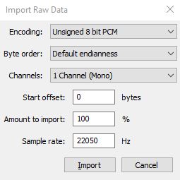 "But I don't know the sample rate" I hear you say. I use trial & error until it sound right in the editor, starting at 22050 and 24000Hz then check if sample count equals file size.
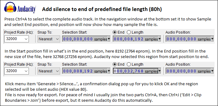
A way to add silence and correct length to samples
Manually edit files
Since I already use Notepad++ to create this web page I only had to add the HEX puggin from the plugin manager. Now I can read and manually edit .BIN files before burning.
Combining samples
Software for my EPROM programmer let me program the EPROM in portions. But I prefer combining all the sounds to a single file before transferring it to the programmer.
From console windows (cmd on Windows) we can combine .BIN files with the copy /binary command like this:
copy /b sound1.bin+sound2.bin MySound.bin
What's special about Unsigned PCM?
As nearly everything I talk about I’m no authority on this topic eider. But my understanding at this time are that it’s only the way we interpret all the zeros and ones we write or read to/from any type of memory or data storage.
With 8-bit Unsigned our data are referred to as numeric numbers between 0 and 255. Signed values are -128 to 127.
If you’re like me you mess around with unknown audio files in WAV editors and accidently find yourself with a visual representation of an audio file where there are no data below the Zero line. Opening a unsigned file as signed could give result like that.
RAW Headless just means the audio file is not an container where information about the content of the file like audio sample rate, bit depth or typical tags like name of song etc. are present. Which after all are pointless in an EPROM device where firmware usually are hard coded and know what to expect at any predefined address.
Sequencer Trigger Inputs
This 16pin IC socket used as cable connector interconnect sequencer inputs to the edge connectors for the voice cards. Pins are connected logical as a normal IC, pin 1 to channel 1, pin 2 to channel 2 and so on. Pin 13-16 are not used.
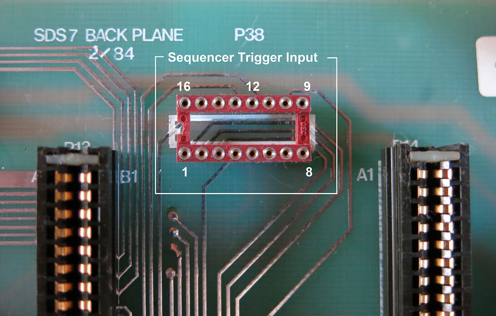
Looking at the PCB traces and where the connector is located one are fooled to believe triggers also connects to the CPU board. But they are actually running underneath the CPU edge socket. Easy way to hook up an internal sequencer or MIDI trigger if needed.Possible why Simmons took the trouble with the long ribbon cable.
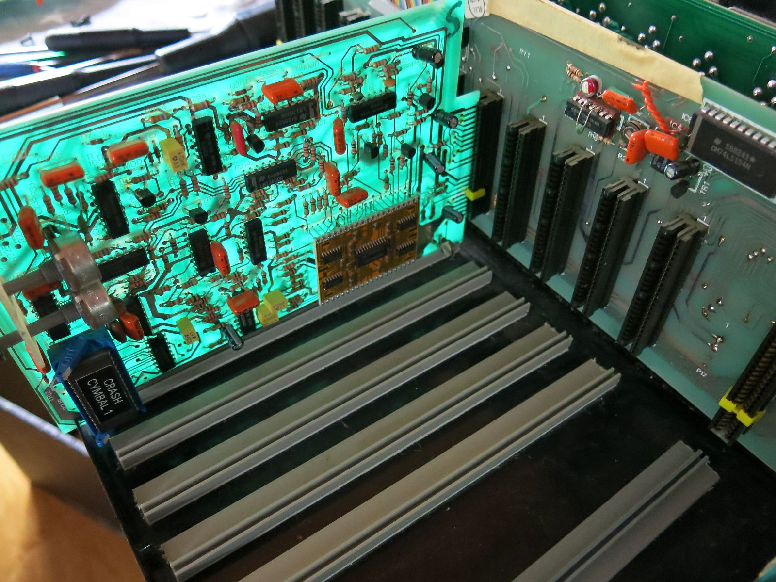
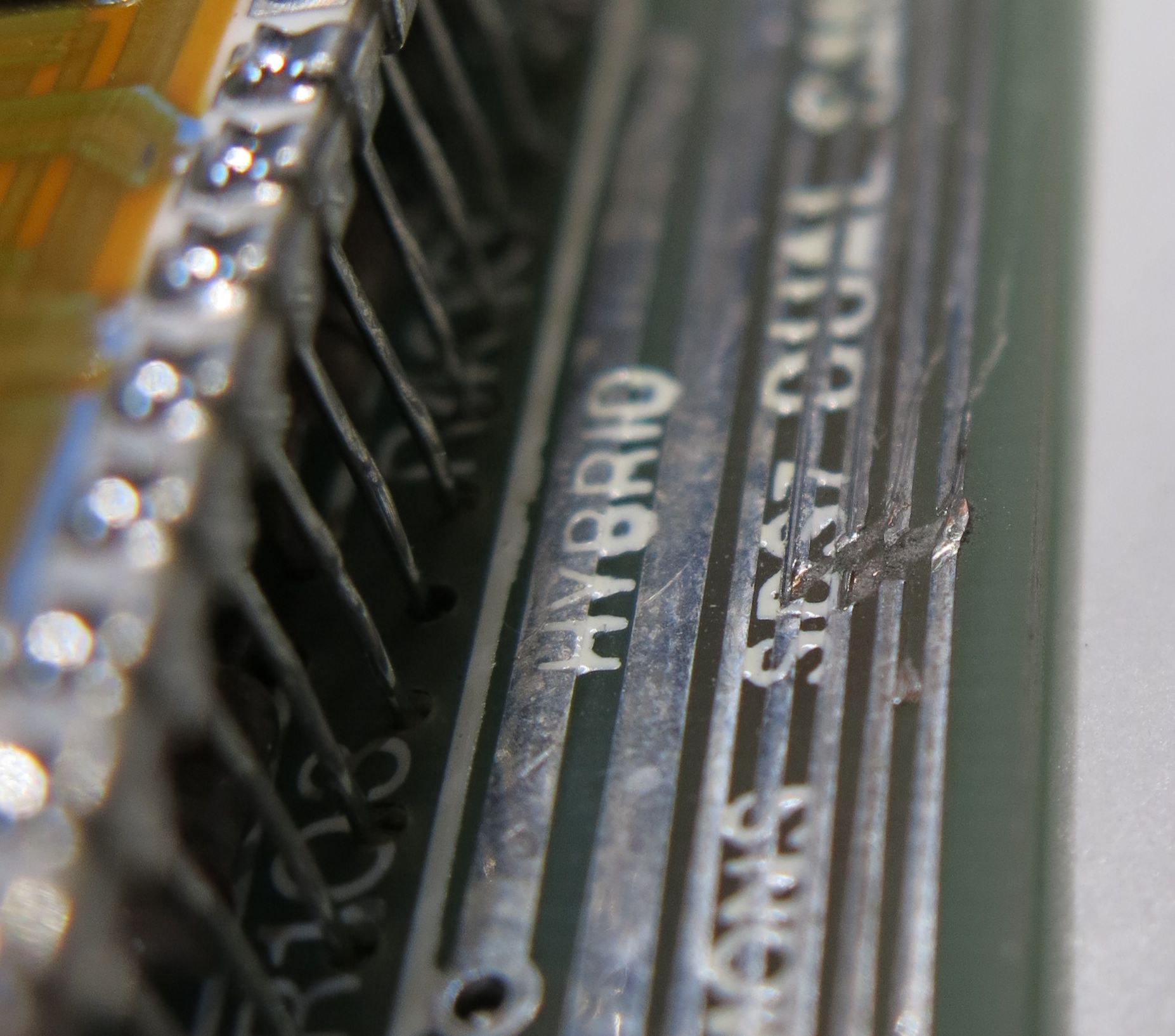
Hybrid Module
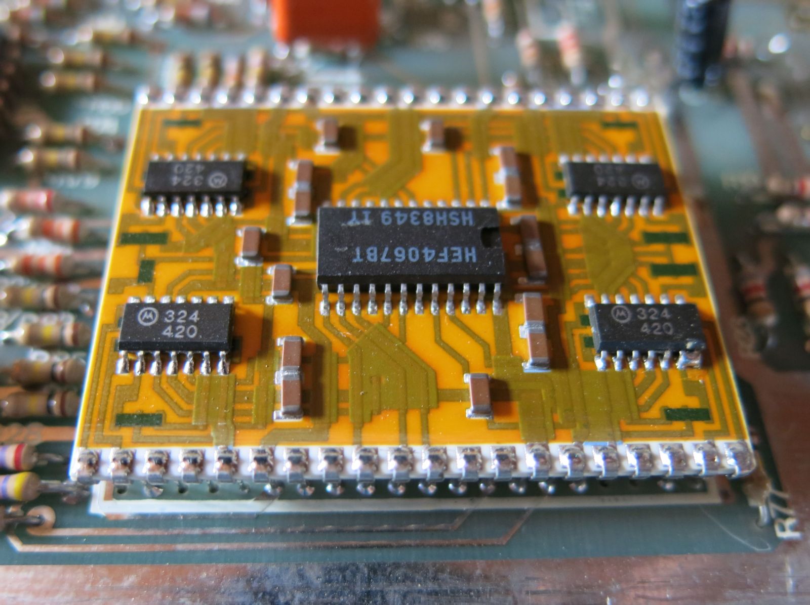
This mystery module labeled Hybrid found on each voice board is responsible for decoding the single CV line coming from CPU board into 15 individual control voltages for the voice board. Burst refresh rate is approx 7300 times a second.
On the backside there are 8 VCA (voltage controlled amplifier).
Accessories
There exist an EPROM adapter card for the Analog/Digital voice board called 2085 daughter board which can hold 4 EPROMs. Friendly members on the Yahoo Simmons list helped me piece together historical and new technical information for this board. Now posted with the EPROM modification
After marked memory cartridges has been made as a personal project where some units where produced and sold to community members.
The blue low profile Zero Insertion Force Socket shown in some of the pictures on this page where actually sold as accessory to simplify eprom replacement.
69 sounds on separate eproms where officially release according to an English flyer where SDS EPB (Simmons Digital Sampler E-Prom Blower), MTM and SDS 7 are on display.
Rubber Feet
These rubber 'feet' at the center rails for the back pane inside the case lid where retrofitted later in production. Mine is dried out and no longer flexing, I cut some springy packaging material I had laying around and glued in.
Pitch raise when entering edit mode
On my unit I've discovered that Pitch and Bend raises ever so slightly when entering edit mode.
Doesn’t matter which parameter I enter edit mode for. As all cards have the problem it seem like the CPU board do something funky and alter the reference voltage for the control voltage DAC when in edit mode.
Working with normal and shorter percussive sounds this isn’t intrusive, I’m guessing it’s simply part of the charm with the SDS 7 when I try to edit longer drop tones with low resolution samples.
One easy way to check for this is to set a long Decay time, lower the pitch of the digital voice until the sample nearly stop playing. Now try stepping out and in of Pitch adjustment several times and hear if the sample run faster when in edit mode. If so, try entering edit mode for any of the parameters and listen.
The nature of being analog
When sharing presets or copying presets between cards there are no guaranty you can duplicate the sound 100% accurate. The nature of being analog and why so many love the sound of analog synthesis are the inconsistency that comes with it. Typical precision of components are +/-5% for resistors and +/-20% for the caps used throughout the SDS 7 circuits, as in most synths and commercial electronics of its time.
I found that my 5 Analog/Digital card differ so much between each voice card I have to take into account +/- 3 for many of the settings I want to copy from one card to another. Tuning two cards to play together in harmony with long decay can prove difficult.
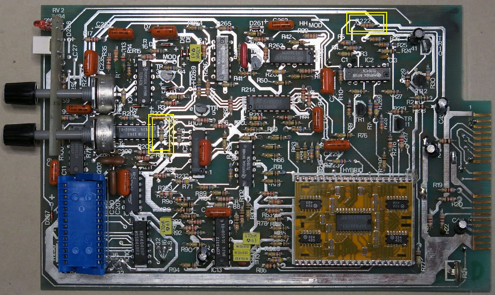
One more for the backlog, modify R222 (82k) and R206 (150k) with trimmers for calibration of voice tuning.
Digital voice - Being square
This is how SDS 7 output a square waveform sample, 55Hz at 8000 sample rate generated with no aliasing in Audacity. Waveform keep this shape independent of pitch. Filter are full open and Modulation speed and amount to zero.
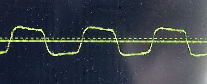
Actually SDS 7 doesn't start the sample bang on when triggered, it fades in starting out as a sinus waveform.
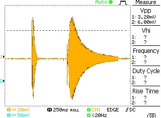
This layered screen dump from my scope try to visualize two audio pulses from direct out with identical settings except decay. Sample is square waveform 1000Hz 441000 sample rate played with high pitch. Click is set to 255 seen as a single line in the beginning of the pulse. Left pulse Decay=0, Right pulse Decay=255. Sadly the Decay do not only change the length of the tone, long decay time also soften the attack. This is also true for the analog oscillator, clearly a function of the envelope generator.
Digital voice - Sounds
Here are a few Simmons compatible .BIN files I’ve compiled with Audacity, ready to be burned with a standard EPROM programmer.
When original sample contributor is known credits are found in the ‘readme.txt’ found in the compressed ‘zip’ files.
SimmonsBIN-EMU Drumulator.zip
SimmonsBIN-LinnEPROM.zip
SimmonsBIN-Miami_Vice_Snare(27128).zip
SimmonsBIN-Roland707-909.zip
SimmonsBIN-SoundsFromMySDS7.zip
Selector Pad
Underneath the rubber surface we find the actual internals for the selector pad glued to the top of metal chassis. It's a 4x4 membrane switch consisting of two layer of plastic film with electric conducting surfaces which short as blade switches when pressure are applied.
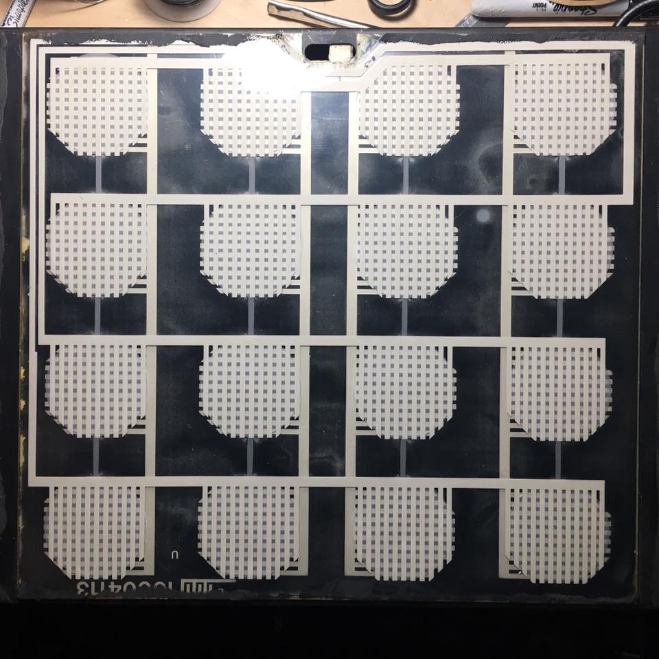 Kudos to Ed Rose for right to use photo
Sadly they're nearly impossible to repair if/when oxidation start to damage contact surfaces. One possible repair route might be to use single thin film membrane switches to replace the damaged area.
MIDI to Trigger interface
Simmons made the MTM module to handle trigger to MIDI and MIDI to trigger. Below is my poor mans DIY attempt.
Work in progress, not tested yet. Note that quick and dirty test platform with Arduino on a Nano board will only give 5 Volt trigger outs. A proper MIDI interface with velocity will need DAC's and op-amps for level shifting.
My Arduino sketch so far DrumTrigger.ino

Debouncing Switches
It is not possible to use the somewhat flawed but ever popular trick soldering a cap over the switch contacts. Doing so will only stall the CPU at boot, and the display goes dark. Please don’t ask how I know. Anyway, this got me curious as to why this happened.
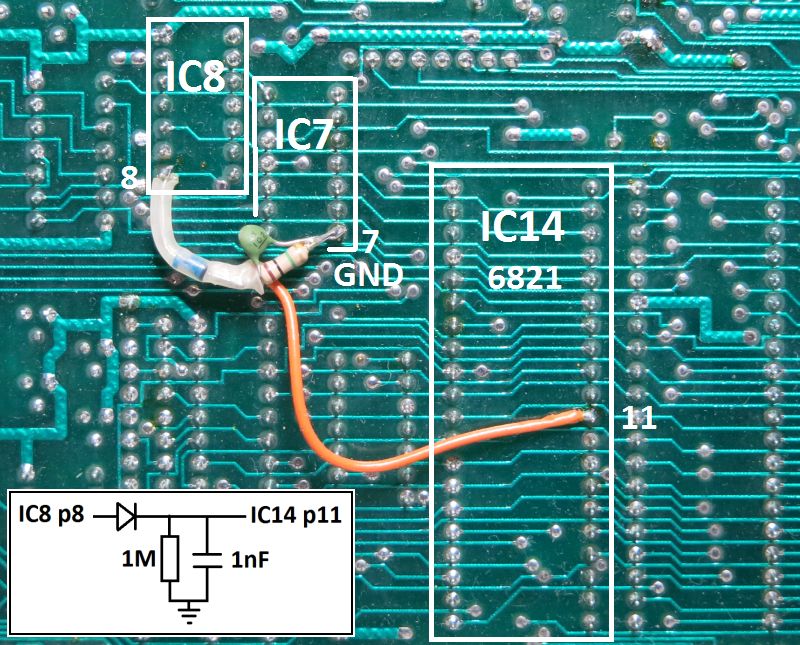
Schematics I have access to are nearly impossible to read and the in/out area in question are not redrawn in the JPG file I got. But to me it looks like all the switches are connected directly as 4 by 4 rows to peripheral port A p2 to p9 on IC14 (6821). To create an interrupt signal when a switch is pressed 4 of the rows are also connected to p9, p10, p12, p13 on IC8 (74LS20). Output on p8 goes to p13 on IC7 (74LS04) and inverted output p12 are feed to interupt pin18 on IC14.
When Simmons replaced the optical fly wheel with the click encoder they had to rework the firmware (version 10, yellow dot on eprom). As it turns out they managed to mess up the debounce code for the switches accumulating in a service bulletin showing us how to implement debounche with hardware. As you will see from this bulletin text it is not consistent with my interpretation of the schematics as it exclude the inverting stage at IC7 and do no longer use the dedicated interrupt pin of 6821. Simmons probably early on changed the interrupt to be controlled by software to cheaply compensate for bounching switches.
Step 1: Remove wire link between p8 IC8 and p11 IC18
Step 2: Add diode between p8 IC8 and p11 IC14. Add 1M resistor and 1nF capacitator between pin 11 IC14 and ground.
Simmons SDS 7 Service Bulletin 10/1/85
If memory is lost there will be no sound
Following tip from the user manual might be useful for new users
Sadly nearly everything defaults to zero when memory is lost. Start with opening the Filter and Level for quicker result.“If all the control valves are half way i.e. 120-150 then the module will produce sound.”
Simmons SDS 7 user manual
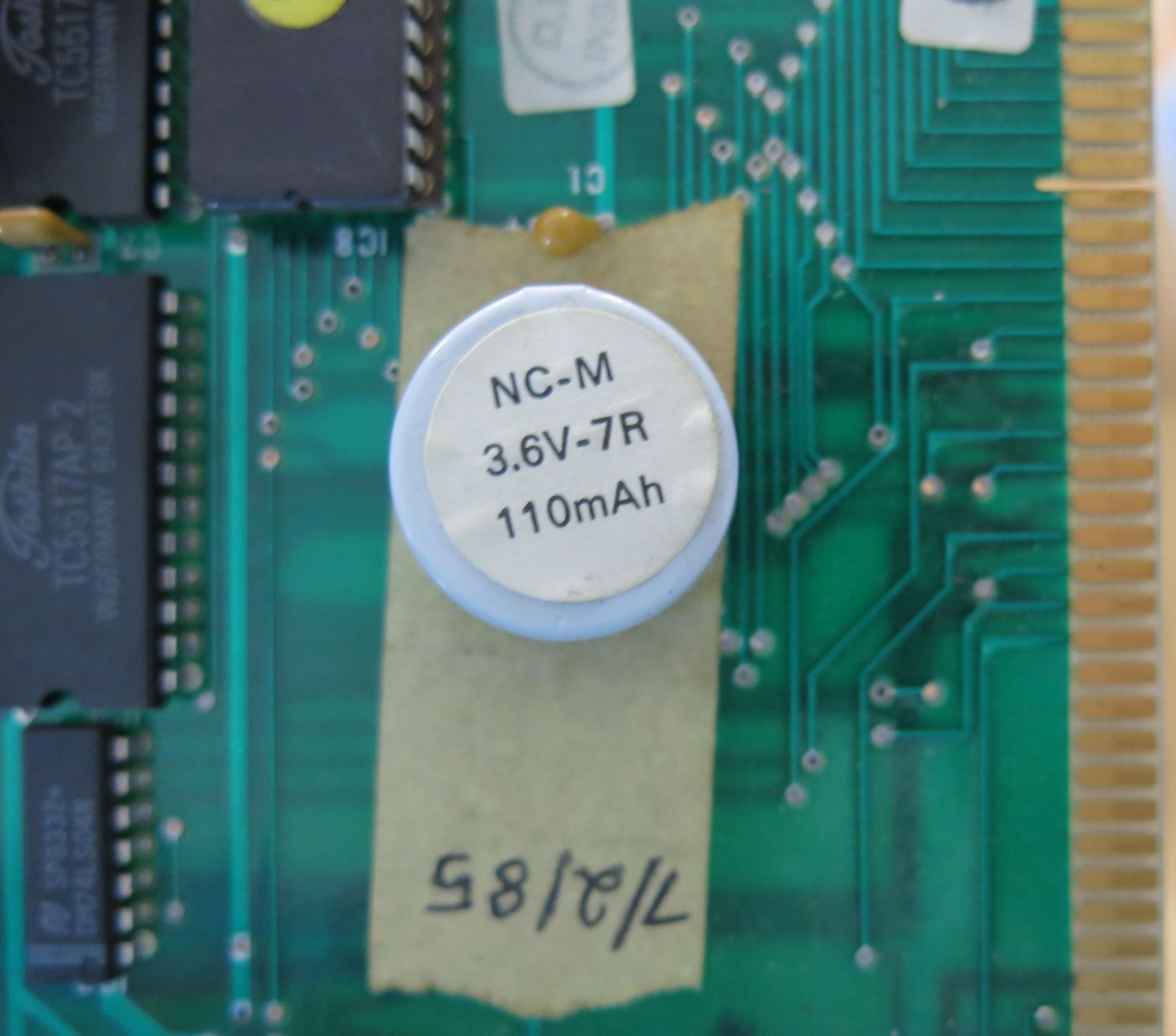
Backup Battery
Stock battery in my SDS 7 was a rechargeable 3.6V 110mAh NiCad. Modern replacement battery is a 3 cell 3.6V Ni-MH rechargeable backup battery, typical around 150mAh. mAh (milliampere hour) are not critical, but no need to overdo it. Anything between 100-200mAh should be fine.
I’ve read warnings that Ni-MH need much lover charging current than NiCad and Ni-MH therefore might overcook. There aren’t an intelligent charger or current limiter in SDS 7, charging voltage on my unit show an average 4.08V without battery connected. That’s 1.36V/Cell (Ni-MH tolerance 1.4-1.6V/Cell) which doesn’t mean that much as it turns out.
It might be wise to check the battery a couple of times the first year after replacement to see that it has not accumulated problems. I’ve noticed eBay sellers list identical battery packages as both NiCad and Ni-MH.”Whereas with lithium ion and lead acid batteries you can control overcharge by just setting a maximum charge voltage, the nickel based batteries don't have a "float charge" voltage. So the charging is based on forcing current through the battery. The voltage to do this is not fixed in stone like it is for the other batteries.”
Battery leakage might be a concern and are often addressed using disposable Lithium long life batteries (not to be confused with rechargeable Lithium-ion batteries). While lithium batteries are not very prone to leakages I’m told they do hold the equivalent power of TNT explosives as its own mass. And that is the bomb that will explode inside your synth if you solder a lithium battery into a charging circuit. Reason is that lithium cells are not designed to ventilate which are necessary for gas disposal when charging. Same reason why you should never ever solder directly onto a lithium battery.
A popular workaround is to connect a diode on the battery positive, blocking current going into the battery. While using a blocking diode is simple it makes for a voltage drop around 0.6Volt. That loss equals some 15 years on the shelf self-discharging for the battery and a lot more In practical application. Brute force solution could be to use higher capacity battery. Better solution would be to disable the charger if possible. Less explosives inside your vintage synth has to be considered a good thing, right?
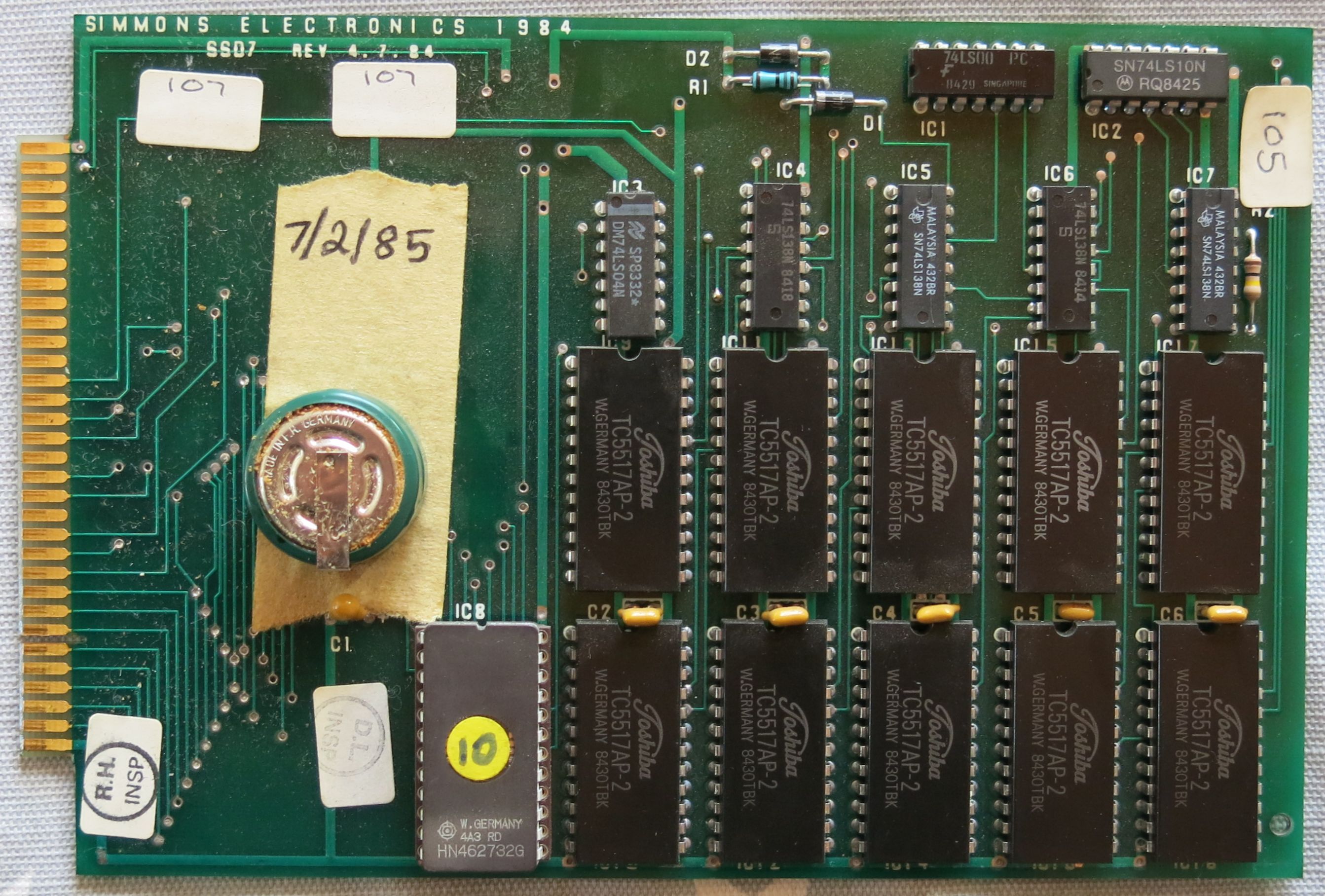
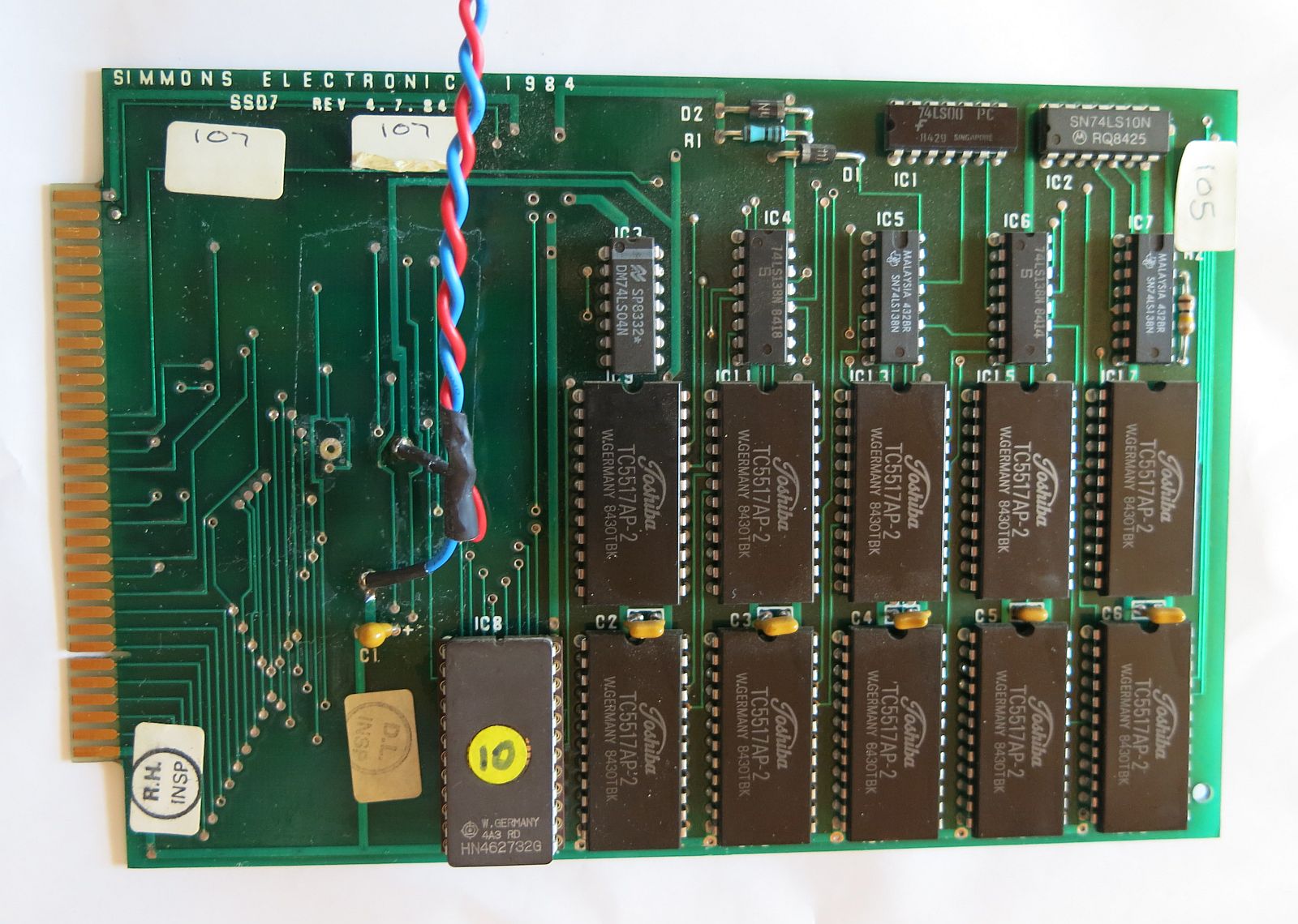
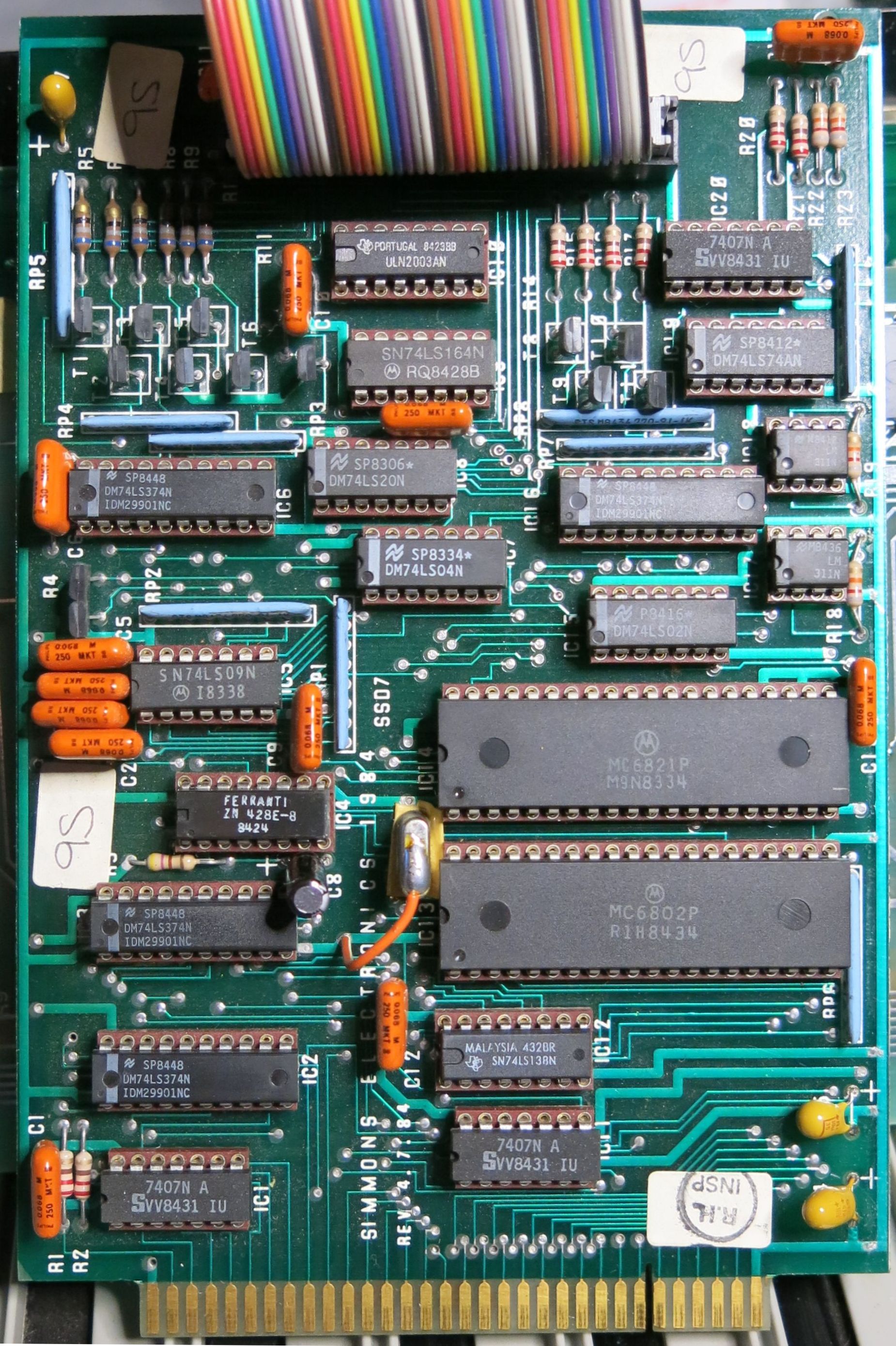
CPU board, “The brainless computer”
It is a bit overwhelming when looking at the CPU board for the first time. Realizing this board is completely ignorant on how you play or trigger your SDS 7 shoulders feels more relaxed. It doesn’t even know, or care where or how many voice card are installed. It will do its job pushing out voice parameter data in predefined order independed if there is zero or twelve voice cards slotted. It start with slot 1, burst out all 15 stored parameters in same sequence as we read them on panel from top left to right. Then move on to slot 2, pull all values from memory and send them as control voltages again and repeat this for all 12 slots before it start over.
Actually most of the bits on here are for the display and tactile buttons on the control panel. Then there is an 8-bit interface for the memory board and a few pieces to send/buffer data and control voltages to the bus-board.
On my revision 4.7.84 board every single IC are socketed, making it real easy to troubleshoot if needed. Many of the buffers and address latching IC’s are in multiples, makes for fast part swapping to check if any faults move with the part being moved. With the danger of destroying yet another part if there is a short or over voltage causing the trouble.
Looking at how simple functionality this CPU / Memory board combination have by today's standard it’s tempting to make a new control panel with 15 CV knobs rather than those clumsy double triggering buttons and single fly wheel. I do like the futuristic look of the panel, but I do not like to operate it. Thats why I aimed to document all the pins with enough techinal descriptions to start coding a MCU developer board.
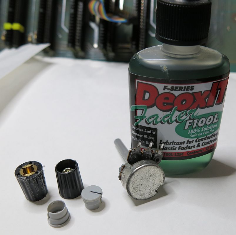
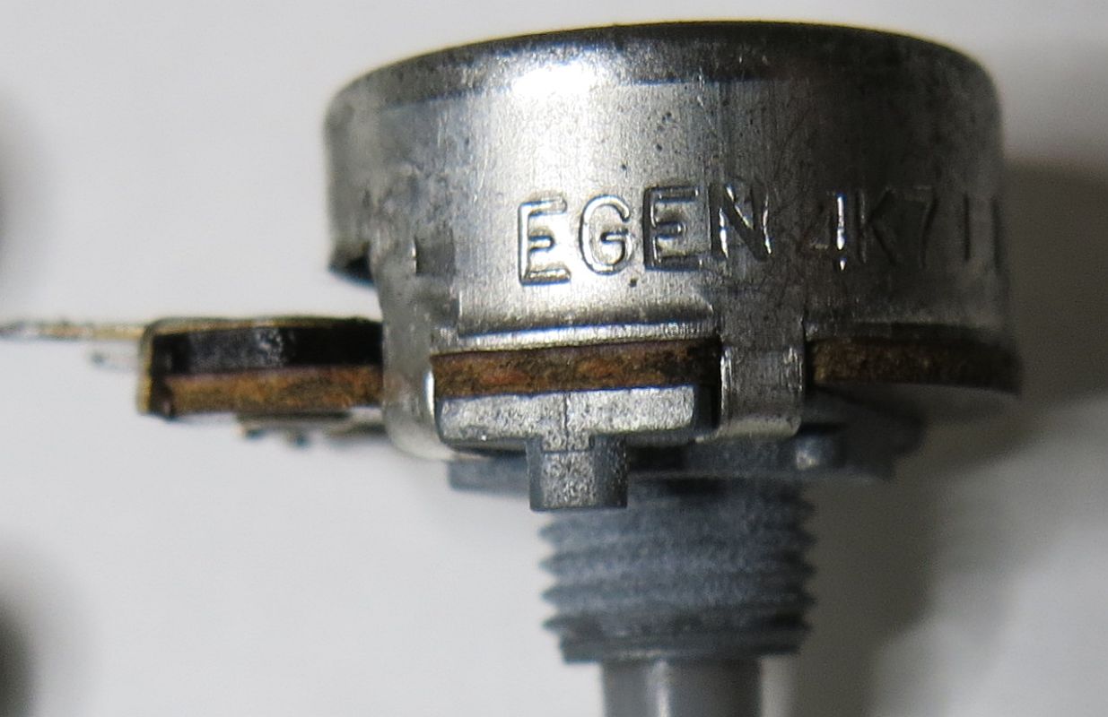
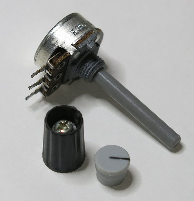
Potentiometers
Each voice card has two pots (potentiometers). Upper pot adjust trigger pad sensitivity. Lower pot is the channel volume control. It also control direct out. There is a pan control for the stereo out implemented with a trimmer R21 on each voice board. For Dual Digital trimmer is labeled VR1.
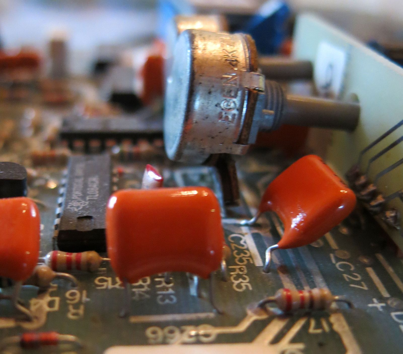
Experience from old devices like SDS 7 is exactly why no-one these days mount potentiometers like they are done here, making them very prone for breaking. And for the same reason why they are rather weird and flimsy to operate.
While the sensitivity control work as expected the volume control doesn’t respond the way I like. Most likely course Simmons in their wisdom used linear taper for both pots.
Depending on how the potentiometer is broken it can simply stop function, can give false triggers, no sound. Volume pot function as master, if broken there will be no signal neither on L+R/Mono or Direct.
Sourcing parts for this today unusual pot with 4x32mm shaft can be challenging. When I’m writing this I luckily (with some help) found two electronic stores I Germany offering ww shipping on their old stocks of pots. Search for 4.7k lin 4mm Omeg Potentiometer PC16BU or Radiohm equivalent CIP160C-KS. Space between legs (pitch) is 5mm.
As I said, I would prefer logarithmic potentiometer for the volume position if you can choose taper when ordering.

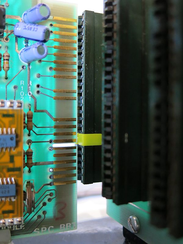
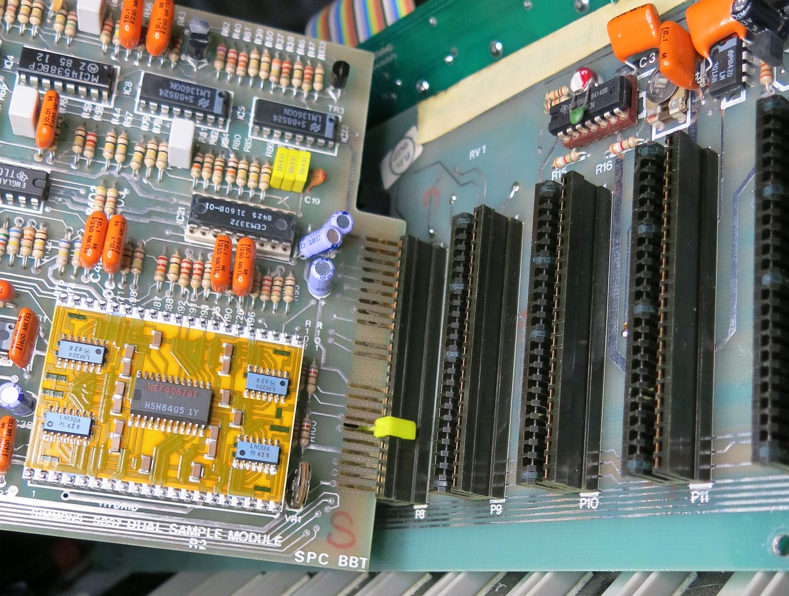
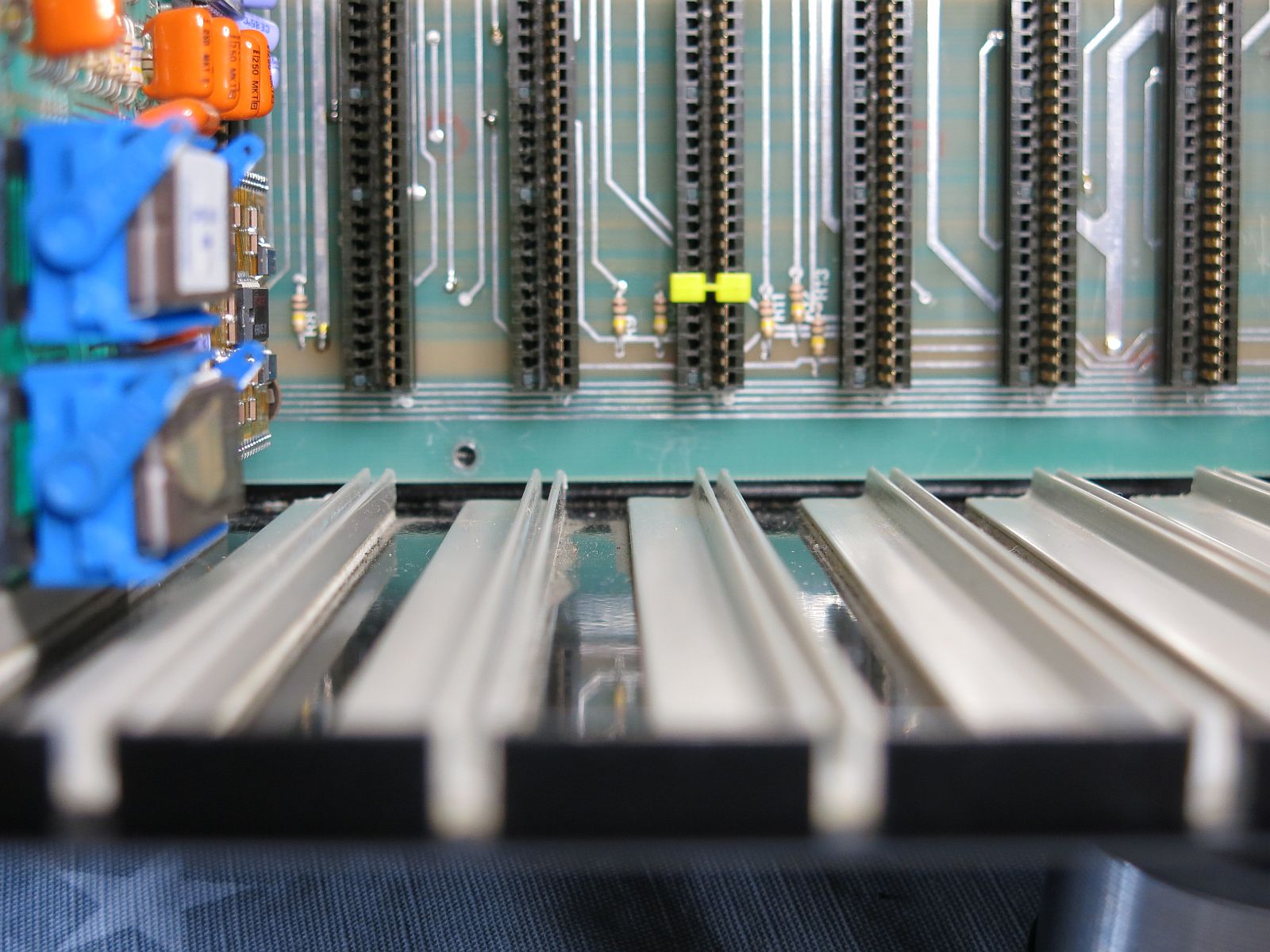
Common fault on SDS 7 is contact issues between boards and the bus-board/back plane
Often in conjunction with transport but can even occur while removing or inserting voice cards, typically when experimenting with EPROMs. Randomly memory loss is believed to come from this contact problem.
On my unit I’ve found (with front panel removed) cards are slipping out on top of the edge connector when chassis is warped only a few millimeters. Investigating this further with the case lid removed I found that while the bus-board is rigid firmly in place in the back, all voice card and CPU/mem board are resting on the bottom plate that are able to flex.
To add to this problem slots for CPU and memory card are not at the same level as all the voice boards. If I mount only the memory board on the right and a single voice board in center, then the screw holes for the bus-board does not align. While rightmost screw hole align perfectly, leftmost screw hole now misalign by more than 2mm. Knowing distance between contact points on the edge connector is 2.54mm (pitch) we see how that might be a problem if voice card is resting on the bottom plate 2mm below its intended contact points.
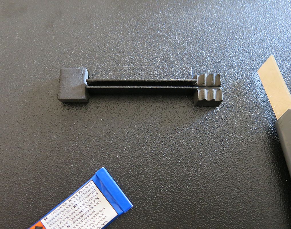
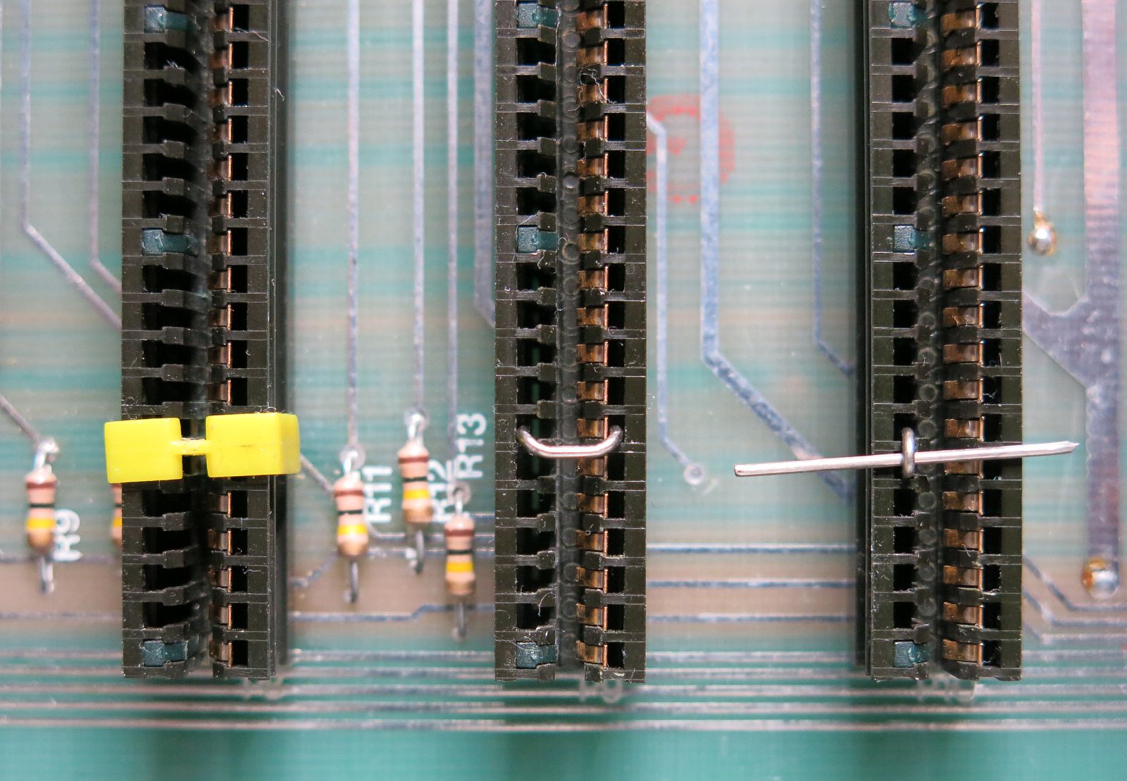
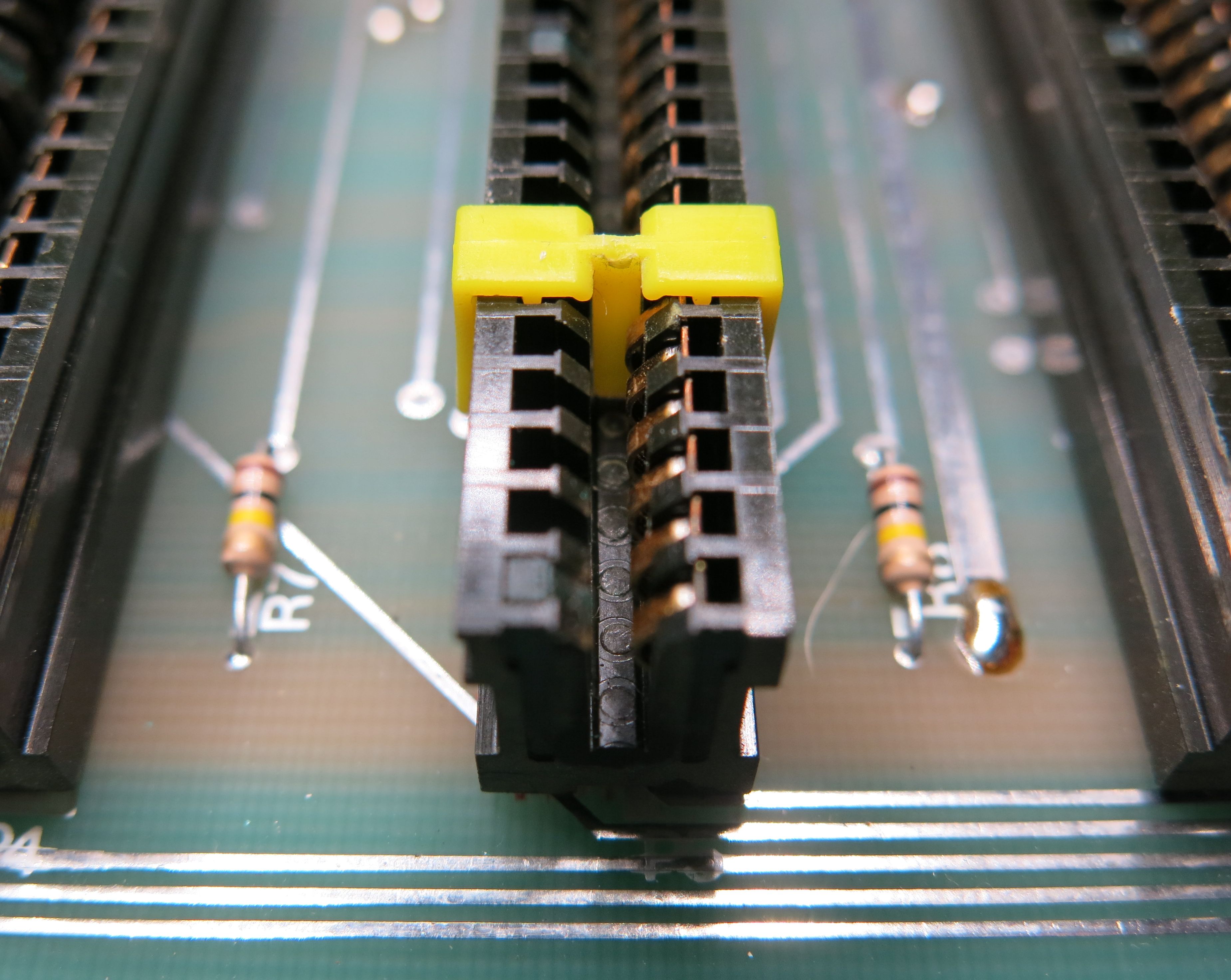
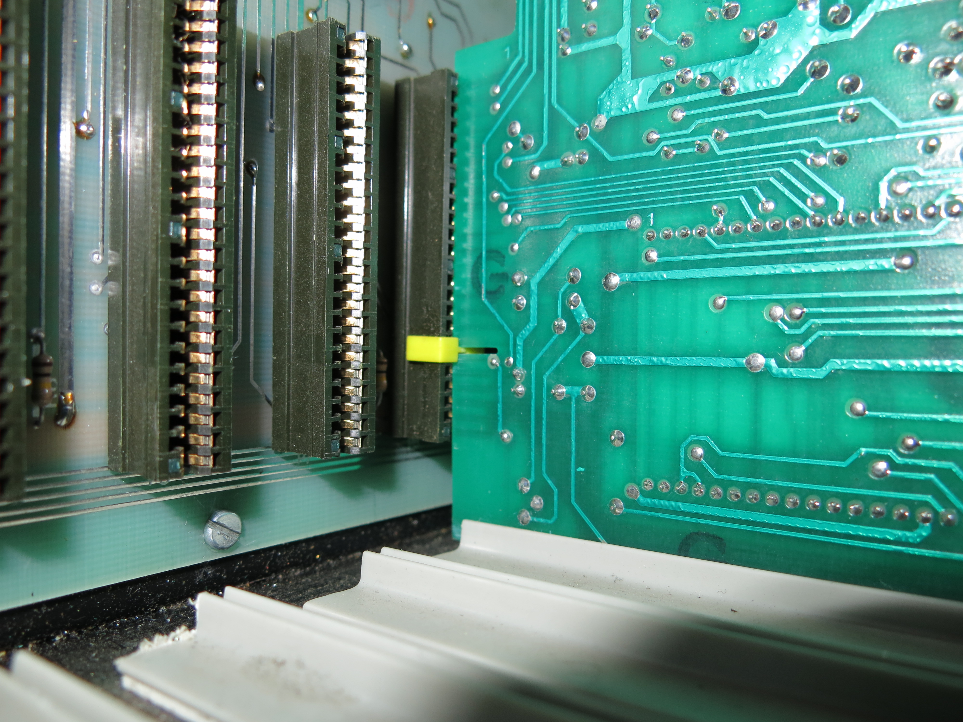
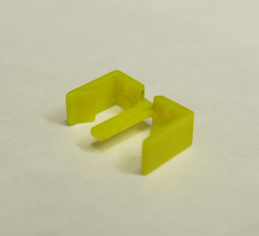
Importance of the yellow keys cannot be stressed enough. Simmons also focused on these in their service bulletin. Even with boards seated with the few keys I have, on my unit I’ve now tested that voice cards will not be able to be fully seated on top of the bus connectors. When reseated they operate, but they are very prone to loose contact when SDS 7 cabinet is moved and the chassis get slightly skewed.
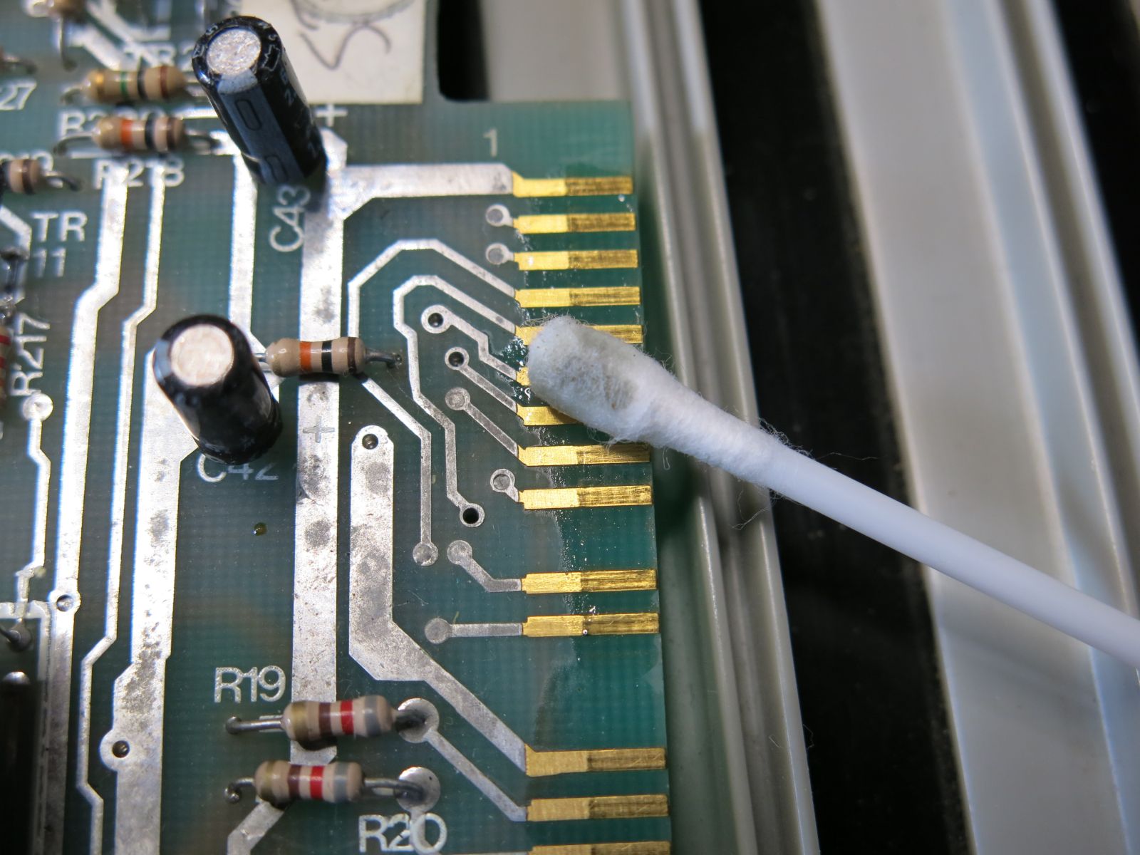
Despite bus-board contact pins and the PCB edge have good quality gold plating they do accumulate dirt and need a good cleaning now and then.
Although temped to rip out all the plastic rails for the voice cards and insert a 1.5m steel plate to raise the rails and simultaneous add strength to the bottom plate I’m know considering just use a thicker elastic tape to raise the voice cards rails to compensate for the height difference between CPU/Mem and voice boards.

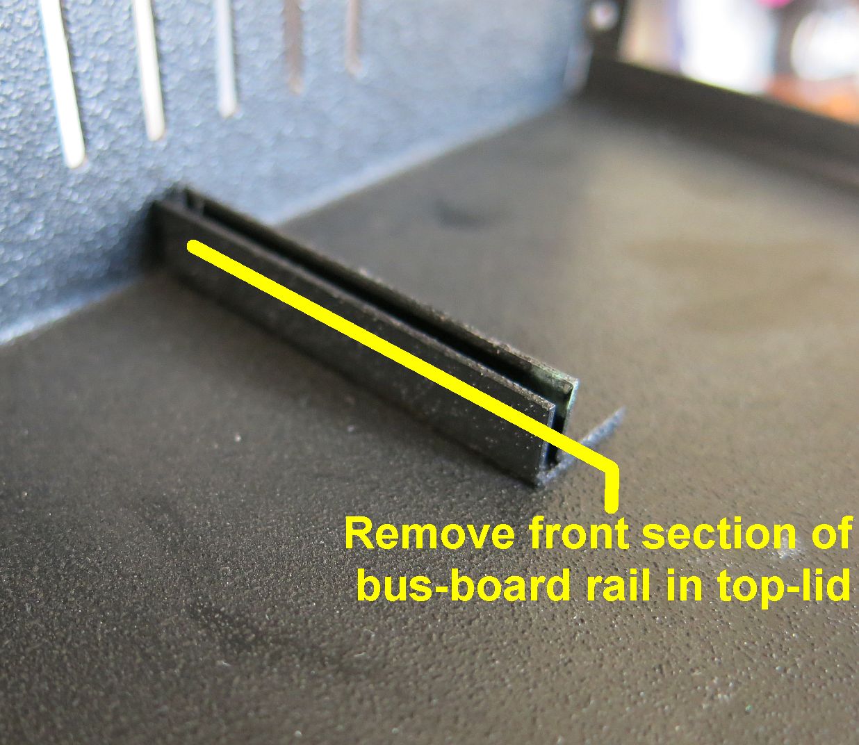
I had this idea to float the bus-board, mount it on soft silicon rubber pins and allow it to flex with the chassis and cards. For this to work I need to do some metal work in the case lid, remove front lip for the back-plane rails. Leaving the back-support and glue in some soft rubber to make pressure from behind, to push the back-plane against all the cards. I will also need all the yellow keys which I do not possess. This idea is on hold.
Michael Buchner where kind to share a service bulleting with me, where among several know issues Simmons did rethink how they mounted the bottom rails. They started out first using double sided tape, later they changed this to glue that proved to fail early on. Probably due to how the flexing of the bottom metal plate and plastic rails differs mechanically and with heat. They went back to using double sided tape.
Faults, more bus-board / back-plane subjects
Pad Trigger not working on channel 3
Found pin 19 for the Pad Trigger bent into the edge socket.
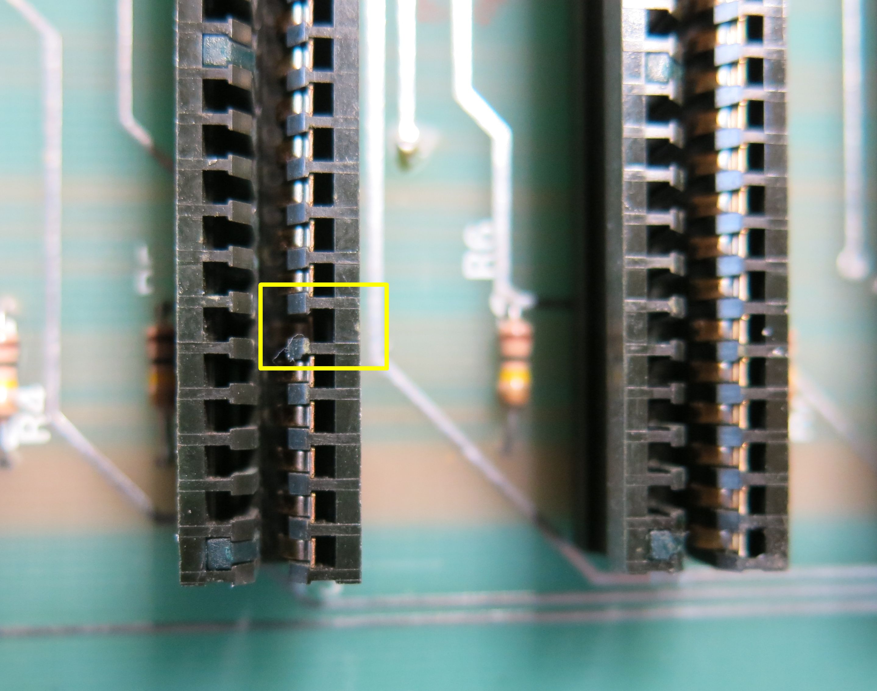
My theory is that this happened doe to the yellow key supposed to be there at some moment in time got stuck to the voice board and pushed into the socket misaligned and thereby destroying the pin.
Luckily I was able to rescue the pin, but had the idea that I probably could desolder the connector and move one of the free pins to this location.
Sequencer Trigger input triggers channel 7 and 8 simultaneous
Found a short on the bus-board, where a ‘via’ soldering shorted a trace running close to it.
Can’t believe that one passed quality control so my thinking is someone in the past three decades have touch up soldering joints missing the fact they made a fault on these channels, probably not using these inputs.
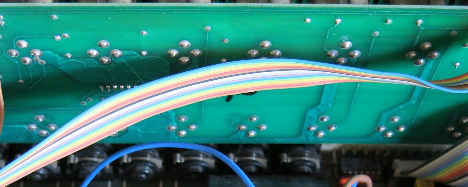
Loose wire
Reason for this wire hanging on the back of the bus-board is to pick up ‘computer noise’ from the databus.
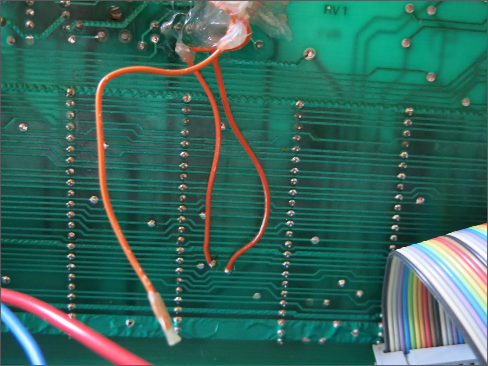
According to the service bulletin this antenna should be taped to the bus-board between channel 9-10. Signal from this antenna is amplified, phase reversed and fed back into the stereo summing amp to cancel noise. Similar to how noise canceling head phones works. Thanks to Michael Buchner for mail support and SB.
Faults II – Dual Digital voice card subjects
Program LED does not turn on when card is selected No trigger from sequencer input
Only sign of life is the Yellow LED.
Found 3 traces damaged. Both cathode and anode for the program led, and seq. trigger input from edge connector cut.
Maybe someone dropped the card?
Digital voice #2 sample doesn’t decay correctly
Tested with several EPROMs, first one I tested with sounded like it looped 4 times before it decayed. Although I learned it didn't when moving on to another EPROM.
Previous owner had bend 3 legs when inserting the ZIF socket.
Voice card appears dead
This one fooled me for the longest time. Card was initially repaired and tested ok with slot 1. When assembling the brain again I positioned it in slot 10 where now the yellow LED turned out to be dead and card non function. Reseating the card several times didn’t help. Back to slot 1 tested OK again. Then take everything apart again to trouble shoot slot 10 without finding any faults.

Long story short, grinding off most of the excessive tin lumps on the ground plane on the back of the edge connector solved the problem. My initial thinking this tin helped pushing the contact pins against the contact element in the edge connector proved wrong. All it does is create uneven pressure for the edge pins.
No sample playback from digital voice #2
Only digital clock noise from voice #2, varying with pitch adjustment.
Eprom was inserted the wrong way, got really hot as power where on for hours before I started working on this card.
This card got me fooled for hours as the EPROM I replaced with, taken from another card also where damaged.
Service note - SDS7 with serial numbers 0-100 can re-set when hot
Two resistors for the CPU startup sequence on the power supply circuit changed.
R4 = 1M5 from 2M1
R6 = 8k2 from 10k
Raw Rambling - Filter full open
My Top 853 programmer notes
DO NOT BUY ONE!
TopWin6 website is long gone and development stopped.
TopWin6.exe only support Windows 32 bit. I keep an old XP machine around for occasions like this.
I’ve measured output from 34063AP1 step-up converter inside the programmer to 12.47V. Program voltage on EPROM chip is 12.4V. I consider replacing a resistor in the feedback loop with a trimmer to tune it closer to 12.75V.
Will only work with 27C cmos series EPROMs with max 12.7V programming voltage.
For EPROM STMicroelectronics M27C256B-12F1 / M27C256B-10F1 select generic 27C256 12.7V under unknown brand. Under Config set Delay to 1ms. Despite what you might think, longer delay do not work.

Sampling memory in perspective
While researching pin configuration for EPROM sizes I come to think of Akai S700 12bit sampler I had back in the late ’80. More specific I thought of some great drum sound I sampled from pieces of my acoustic kit inside a big concrete car park.
This sampler used some rare 2.8” floppy disk called Quick Disk. I remember two packs of 10 empty disks set me back more than a week salary. With its whopping capacity of 128k bit that usually meant one disk/one very short sound. Think of it, in comparison a 512k bit EPROM with 8bit samples in SDS 7 can almost ’last forever’ without looping. If we only could find a way to change samples easily.
Another historical fact that popped up on the wiki, the invention and first commercially use of floppy disk and EPROM are both dated to 1971.
Noise Machine
Demonstrating use of gate signal with SDS 7.
Gate are activated using a 9V battery connected to a micro switch into sequencer input. Pitch shifting is all done by SDS 7 bend/modulation preset without external CV control.
Be prepared for unpredictably behavior. I've not figured out how the envelope trigger with gate signal. With long deacay you can hear the sample clock generator runnings for lengt of sample without envelope opening. Sometimes I get click similar to Click generator even when its set to zero. This seems to differ between voice cards.
Thanks to
A lot of what you read on this page derives from schematics Thierry Epherre made while reverse engineering the Analog/Digital voice board. Thanks to Michael Buchner for sharing this and other documents with me.
Although I actually owned a SDS 7 5 piece kit back in the late ’80 early ’90 nearly all the historical facts on this page comes from reading documents found on the web, where Simmonsmuseum.com and Simmons.Synth.Net are the biggest contributors.
Big thank you to developer team behind Notepad++ and Bootstrap framework for making the tools used to create these webpages.
Links
Top of page SDS 7 image directoryManuals, history and more: http://www.simmonsmuseum.com
Looking for used Simmons and parts, Ed Rose is The Simmons Guy located in US: https://www.facebook.com/thesimmonsguy/
SDSV cymbal goes SDS7: http://blog.simmonsmuseum.com/?p=130
Hi-Hat pedal with VC mod: http://www.drummachines.de/beatboxer/stories/sds7hi.htm
Simmons Sounds - Electronic Soundmaker & Computer Music - Jun 1984 http://www.muzines.co.uk/articles/simmons-sounds/3338
Comments
Your comment are welcome
Aaron    2023-03-26 07:07:06
I have a semi functioning SDS7. Thanks for posting this valuable information here. The issue with my unit is that when I try to change/program the sounds with the incrementer nothing happens in that the sounds don't change. The led sequences and led display are working. Any suggestions would be appreciated. Looks like the controller is not updating the sound cards via the 6821, only a guess.
Tim    2021-06-29 04:30:33
hello. I am currently having my battery replaced. the tech is trying to reload the factory kit data but is unable to do so. at first he thought it was the ram but it is apparently something else. can you suggest anything else to test? thank you
Barry Galvin    2020-03-20 23:29:29
I have an SDS7 I am restoring. Your webpage has answered many questions. I have a bad copy of the service manual. Do you have or know where I can get a readable copy?  Thanks, Barry
jason    2018-11-26 00:55:04
I have one of these, machines. I really like your gate video, i like the idea of using these "drum" modules more like synthesizers. Would be cool to take one module and make it more like a synth, knobs real time controls etc, just ditch the simple cpu altogether. Or better yet program a arduniotype device to have more control over 15cv values?
theroude    2018-06-13 22:25:12
Many thanks for your answer
Jean luc
StillNotWorking    2018-06-10 18:15:01
Sorry Jean Luc,I don't have any knowledge on the SDS1000. You might try the Vintage Simmons Yahoo list or FB group.
jean luc theroude    2018-06-10 17:41:42
super
i am a french man and i tried to get the same
things you do
this will be useful for me to understand and try to repair my SDS1000 with lm 324,LM13600, cem 3394
if you have such doc please send me
sincerly yours jean luc