PG-800C::about
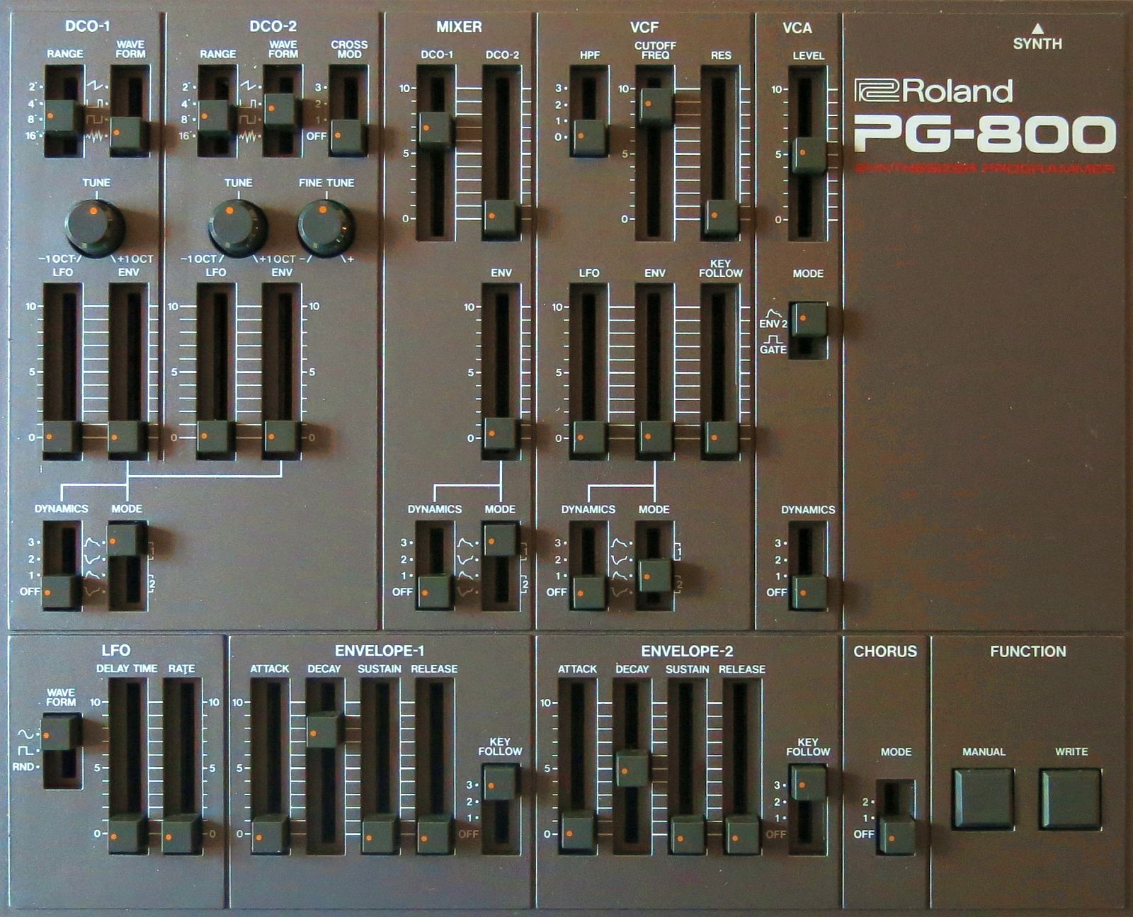
This page is dedicated a FREE open source clone projects for the sought-after PG-800 programmer for Roland Super JX-10, MKS-70 and JX-8P. It’s been done many times before, but I can’t seem to find anyone documenting and sharing how they did it.
Discussion over at Muff Wiggler... soon!
PG-800C::buzz & possibilities
- Ever wanted to tweak sounds on your Super JX-10, MKS-70 or JX-8P synth with real knobs but can’t afford the humongous price tag on PG-800?
- Control your analog monster synth from your modular gear with CV?
- Storing presets on SD cards (somewhat limited use as we can only store setting from PG-800 panel)
- Create USB host with ATmega32U4 board so you can use modern midi controllers without proper midi connector to alter sounds on PG800 port.
- How about using a ESP Series MCU to create a Wi-Fi receiver to alter sound parameters on JX/MKS over your Wi-Fi network?
PG-800C::buzz for PG-800 owners
- Merge CV inputs with PG-800 parameters sent to synth
- Convert PG800 out data to MIDI to work as standard MIDI controller
- Control multiple or selected JX/MKS from one PG-800 without the need for reconnecting wires?
- How about building a better looking and more feature rich controller than the scrappy looking PG-800? Compare design difference with MPG-80 and you understand what I mean.
PG-800C::what this is not!
Sorry, this is not a place to order your complete PG-800 Clone, or parts to build one. Nor is it a single multipurpose dingy doing it all in one box.
PG-800C::bonus
All discussion, schematics and scanner code for the potentiometers in this project can be ported with little or no modifications to a MIDI controller. It is also possible to make the programmer do midi output and PG-800 protocol simultaneous on separate ports. To my knowledge Fred’s JX10/MKS70 firmware from v3 already support this on midi out from the synth.
PG-800C::faq - how much does it cost to build?
It depends what you want to build. A simple interface/converter can be done for 5US$ excluding cabinet. Using landfill quality parts from eBay with hand drilled face plate and printed paper panel one can realize a 44 pot controller for less than 30US$. That’s how I plan to do my prototype. If you want something nice looking inspired by MPG-80 expect to spend 300US$++.
PG-800C::faq - is it a lot of work to build one?
It depends what you want to build. If you’re aiming for 44 hand wired potentiometers we are talking about a rather tedious job yes. Drilling 50+ holes is probably the biggest obstacle for most of us. A simple repeater, midi converter or SD storage device is a much simpler project.
PG-800C::faq - can I make this work without any programmer experience?
If you know how to install a USB driver on to your computer system you should be good to go. That is if you’re satisfied with functionality code shared here and elsewhere will give you.
PG-800C::faq - note on PG-200
As the Roland PG-200 programmer use a similar connector to PG-800 a feasible question would be to ask if we can reuse this design with our JX-3p and MKS-30? Sadly both pin connections and data protocol are different. JX-3p alter pin 6: BUSY when it wants data. PG-200 then send data on pin 5: SIG.
pin 1: -15V | pin 2: +15V | pin 3: +7V | pin 4: GND
From this we can learn that it will be wise to protect all data pins going to/from the external connector. Pin 1 in our PG-800 clone is used to set READY with 5V logic. If connected to -15V on a JX-3p we will kill our ATmega MCU unless we voltage protect its pins.
There is a commercially available clone out there called DT-200. But PG-200 doesn’t seem to be that rare and prices aren’t that silly yet. Remember you get a quite a bunch of nice chrome plated knobs and switches with the original PG-200.
With stock JX-3p you have to select if you want to use midi OR PG-200. For any practical use of this synth most of us want to modify it to some extent. Not sure if there is any open source project out there yet, but I’ve seen at least two commercially projects.
PG-800C::files
Compiled and ready to use hex file together witch avrdude downloader can be downloaded here soon...
Together with locally installed virus protection I use https://www.virustotal.com/ to check files I download from internet.
Distribution files explained:
- readme.txt
- – license for the files in this package
- PG800.cpp.hex
- – actual code going into ATMel MCU
- libusb0.dll
- – for Windows allows user space applications to access USB drivers http://sourceforge.net/p/libusb-win32/wiki/Home/
- command_string.txt
- – showing command string example
- CH341SER.EXE
- – Windows driver for popular and now well behaved CH340 USB serial chip used on low cost Arduino boards
- avrdude.exe
- – Windows up/downloader for AMTel MCU. See here for other versions http://download.savannah.gnu.org/releases/avrdude/
- avrdude.conf
- – configuration file for avrdude
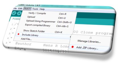
Download latest source code from github https://github.com/StillNotWorking/PG800
Click ‘Download ZIP’ button on right side to grab the complete library with examples ready to install in Arduino IDE.
Source files explained:
- PG800.ino
- - main Arduino sketch
- pg800mem.ino
- - handling preset storage, copy this file to directory where main sketch is
- pg800label.ino
- - for use width LCD, return name for active control, copy this file to directory where main sketch is
- pg800.cpp
- - part of library handling communication with synth
- pg800.h
- - part of library handling communication with synth
- pgconst.h
- - optional if you like have all control names declared as constants
- What pot values should I use.txt
- - information file also includet on project web page
- Thoughts on using switches.txt
- - information file also includet on project web page
PG-800C::panel
Despite having thick clumsy fingers I do love the eurorack format for its ability to cram a lot of functionality into a small form factor. As one of the design goal for this project is to receive Control Voltages why not do a eurorack panel? Of course there is no need for mounting it to a eurorack case therefore those not into walls of modular might still find it useful.
Panel size 3U(12.8mm) x 66HP(335mm) Recommended knob size max 15mm outer diameter. By my experience taller knobs with soft touch are the most comfortable. But usually cost dictate what I end up using.
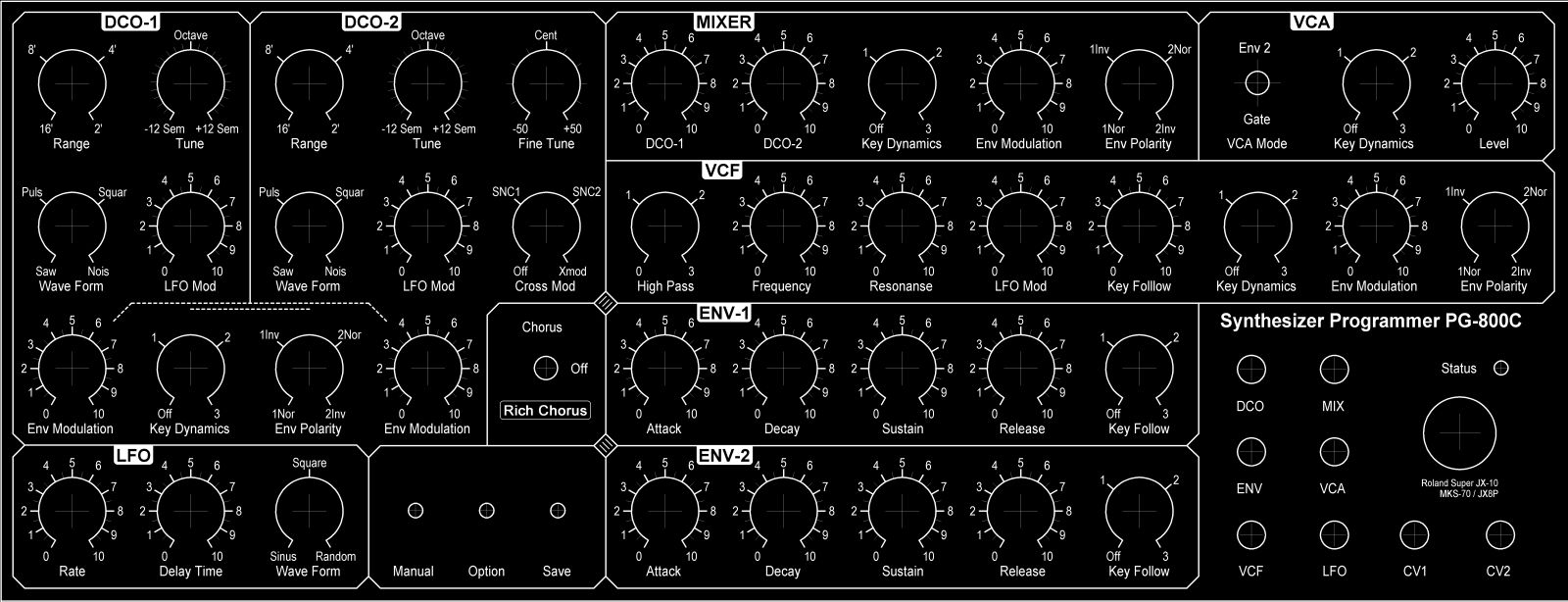

I’ve altered some of the labels for better understanding of what purpose the knob have. Why use ‘Mode’ when you’re talking about ‘Envelope Polarity’? To me as end user that’s like altering new sounds randomly.
Download user panel as high resolution 600dpi TIFF file with Black or White background.
Project files at GitHub will include raw TIFF and Target 3001 file with all the controls for you to lay out at your own liking. Some like to print the graphic file and cut and paste with scissors and glue to come up with they're design.
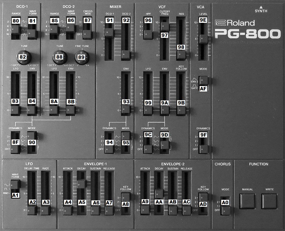
Click image below for an overview of the new panel with control codes.
PG-800C::panel - design tools
I use Target 3001 (free version) https://www.ibfriedrich.com to draw my panel. When finished I export to TIFF at 600dpi. Gave up 1200dpi as the next step become unbearable when zooming into the file.
Target 3001 sometimes mess up text alignment. To correct these errors I found some simple editing possibilities in MS Paint very useful. I use the cut tool to mark around the text and then move the text with the left/right keys one pixel at a time (now you see why 1200dpi get messy). MS Paint is also used to clean up drill lines and adding and moving objects and text.
I’ve successfully used Photoshop Elements to color panels made this way. As long as you save file to TIFF format you are free to move it around in different applications and still maintain quality and scaling.
Not being a Target 3001 wizard I’m wondering if it’s possible to build on my work to create PCB file and front panel ready for order. Possibly we have to draw PCB first, then panel. Anyway, just a thought.
PG-800C::technical - parts used in prototype
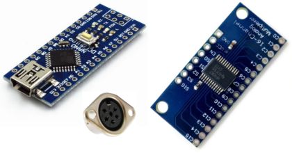
- 1x Nano ATmega328 board (ATmega168 is fine if you don’t care about SD card storage)
- 3x CD74HC4067 boards
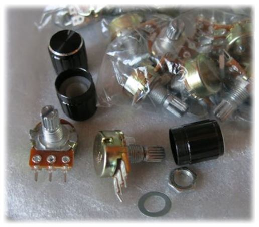
- 44x 10k linear potentiometers - bought a bag with 50 landfill quality pots cheaply off ebay
- 1x 6-pin DIN connector
So far total cost for electronic parts for my PG800 clone prototype is less than 22US$ incl. shipping. It still need a box and knobs though.
Search like ‘Nano ATmega328 16MHz 5V’, ‘CD74HC4067 board’, ‘’50pcs 10k linear pot’ sorted as lowers price incl. shipping should get you close to my figures. Interestingly I often find it to be cheaper to buy them in bulks of 10pcs. I believe this is due to more competition among eBay sellers for smaller quantities.
PG-800C::technical - how it works
Margus (http://www.wolzow.com/) was very kind to share command values and this thorough explanation to get me started back then when I first started plans to clone PG-800:PG800 service routine is called from the main loop (no interrupts involved). Service routine checks whether PG800 has set the PGREADY line denoting a data byte is waiting. If not service routine exits. If yes, JX starts bit-banging. It raises PGCLK signal, waits for PG800 to transmit a bit, and repeats this 8 times.
It then assembles the byte and checks whether this is command byte or data byte. All this is reliant on timing which is done by cycle counting, so the rest of the JX waits. So, from PG800's perspective, when it has something to transmit it raises the flag, and after that sends one bit per clock signal. That's it. IIRC, all the switches on PG800 are actually faders and PG800 scales them to discrete values, but I have to check this.
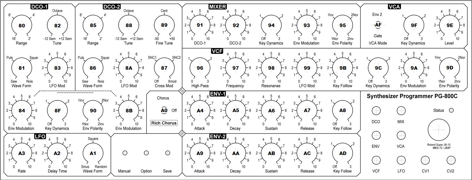
All PG800 commands are two byte sequences, first command byte (MSB = 1), then the value (MSB=0), similar to MIDI CC commands. A received command byte is stored and PG800 service routine exits. A received data (value) byte is sent to voice boards for processing together with command byte. Commands are in range 80..AF (see below), 8D, 8E and AE are not used, 8C (BEND LFO)(*) is only processed by JX-8P.
Thanks Margus!
(*) As far as I can understand there isn't a control to alter 8C (BEND LFO) on my PG-800. Not sure how/if JX-8P owners can utilize this command with they're PG-800? As I’m on JX-10 I don’t have any use for BEND LFO, nor can I test if it’s working. Therefore my panel design will not implement BEND LFO. But source code can easily be changed if needed. I plan to trap 8C, 8D, 8E and AE for CV purposes.
Here is an overview of the panel with all the command values in hexadecimal.
PG-800C::technical - power supply
PG-800 is designed to be powered from main synth. With proper voltage regulator there shouldn't be a problem feeding a modern Arduino board and necessary mux chips from synth's unregulated +7 Volt line found on pin 3.
It is however recommended to implement some sort of current protection (fuse) on the +7 Volt line to protect the synth from any short that might happen while you're building your PG clone. Please read 'What pot values should I use' for other thoughts on power consumption.
PG-800C::technical - what pot values should I use
Multiposition switches on PG-800 are actually short 15mm sliders with dents. If you rather have switches see schematics for Roland's MPG-80 midi controller for inspiration. Just remember to scale resistor values. I’ll post some examples when I have tested data output.
Original PG-800 feed 2.5Volt over 100k pots. Current draw is around 1.1mA total with 44 pots. As ADC inputs on Arduino boards prefer pots in the range 1k-10k we can’t expect to match this number. At least not if we want to connect directly with the input without use of op-amp for impedance matching.
Connected to 5V with 10k pots expected current draw is 22mA. I don’t think we’ll get into trouble even though we load synths power supply 20 times higher with this section of the circuit.
Although we can get power consumption down using lower reference voltage I’m unsure how that might impact on how prone to noise our circuit might get. But on the other side, a good clean and low reference voltage to also feed all pots might be exactly what’s needed here?
| Pots | 10k/227ohm | 5k/114ohm | 1k/23ohm |
|---|---|---|---|
| 5V | 22mA | 44mA | 220mA |
| 3.3V | 15mA | 29mA | 145mA |
| 1.8V | 8mA | 16mA | 80mA |
Here is how we got to those numbers:
5V / 10000 ohm = 0,0005 A * 44 pots = 0,022 A = 22mA
5V / 0,022 A = 227,2727272727273 ohm total resistance for all 44 10k pots in parallel
To better understand how ATmel MCU work out its reference voltage please read: https://www.arduino.cc/en/Reference/AnalogReference
Freddy Alferink has a great article about analog measurements using ATmega328 http://meettechniek.info/embedded/arduino-analog.html
PG-800C::technical - PG-800 connector
Connector used is a standard 6-pin DIN connector ready availably from several sources, including eBay.
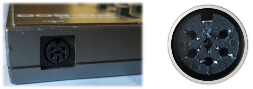
Cable is connected strait one-to-one (i.e. pin 1-1, 2-2, 3-3… and so on).
| PIN | PG-800 | JX-10/MKS-70/JX-3p |
|---|---|---|
| 1 | Ready Out | PG_RDY |
| 2 | +15Volt | +15 Volt out |
| 3 | +7 Volt | +7 Volt out unregulated |
| 4 | GND | GND |
| 5 | Data Out | PG_DATA |
| 6 | Clock In | PG_CLOCK (Clock Out) |
PG-800C::technical - logical levels
For those curios about levels. With JX10 PG800 is communicating directly with synth's main 6303 CPU through digital transistors DTC114/DTA114 on both ends using 5 Volt logic. Having built-in bias resistors these DTC114/DTA114 transistors differ slightly from normal small signal transistors often found in applications like this.
On JX-10 these are labeled Q5, Q6 and Q7 located near the CPU.
PG-800C::technical - CD74HC4067 multiplexer
Originally my first few revisions where written for 6pcs of the 4051 multiplexer chip. To my surprise I later found that there weren’t many developer board easily available for this popular part.
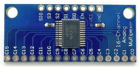
Besides doubling inputs from 8 to 16 4067 also have lower on resistance and faster switching speed. The higher voltage 4051 can handle aren’t needed here so finding those cheap 4067 boards might turn out to be a win win situation for us.
PG-800C::technical - selecting MCU
ATmega328/168 16MHz 5Volt like the Nano are probably the simplest way to start out. But in principle all Arduino/ESP boards having the necessary pin count for your project should work. Remember our vintage synth use 5V logic. Any 3.3V MCU boards will need added complexity with signal leveling.
If you need USB host functionality look for boards with ATmega32U4 MCU like Arduino Pro Micro
PG-800C::technical - don’ts
Many popular ATmega328 projects include loads of blinking LED’s. If that’s your style there is of course nothing wrong with that. Consider using an external power supply and LED multiplex driver for your project not to overload or introduce noise to the synth power line.
PG-800C::technical - CV input
Will post schematic for CV input here. Hopefully we’ll find a generic op-amp developer board we easily can implement.
My plan for the 8 CV inputs on my test panel is to utilize 4 free inputs from CD74HC4067 mux boards. These will work in parallel with the corresponding knob on the panel and can be addressed to any destination from code.
These are the free inputs on the multiplexers:
	actPot: 12(0x8C)  mxc address: [0011]  analog-pin/board: 12/0  BEND LFO
	actPot: 13(0x8D)  mxc address: [1011]  analog-pin/board: 13/0  UNKNOWN
	actPot: 14(0x8E)  mxc address: [0111]  analog-pin/board: 14/0  UNKNOWN
	actPot: 46(0xAE)  mxc address: [0111]  analog-pin/board: 14/2  UNKNOWN
For the last 4 inputs I plan to normalize the panel so that when you put in a 3.5mm jack it will disable the corresponding potentiometer.
PG-800C::code - important note
If code is not running as expected please make sure you have search source code for '!!!' indicating code in need of tuning, complete rewrite or have important information.
PG-800C::code - test output
Below text list debug output on serial port. It list how loop counters in the potentiometer scanner progress and how MCU pins are addressed accordingly to address multiplexer and select correct analog input.
actPot: Active potentiometer based on loop counter with corresponding Command code
mcx/analog-pin: [multiplexer address (i.e. digital pin values)] decimal counter / analog pin selected
newVal/oldVal: show voltage readout on selected analog pin mapped to 0-127 / oldVal is stored value from an earlier loop where this pot was updated
Rightmost column list command label associated with command code. You might notice three of them are listed as unknown at this time
actPot: 0(0x80)  mxc/analog-pin: [0000]0/0  newVal/oldVal: 38/38  DCO1 RANG
actPot: 1(0x81)  mxc/analog-pin: [1000]1/0  newVal/oldVal: 38/38  DCO1 WF
actPot: 2(0x82)  mxc/analog-pin: [0100]2/0  newVal/oldVal: 37/37  DCO1 TUNE
actPot: 3(0x83)  mxc/analog-pin: [1100]3/0  newVal/oldVal: 37/37  DCO1 LFO
...
PG-800C::code - potentiometer scanner speed
My amateur attempt to optimize speed for the scanner code revealed three sections where I could try to optimize.
First part was surprisingly Arduino's own map() function. Purpose of map() is to scale values from the analog to digital converter (ADC) from 0-1023 to values the synth can manage in the range 0-127.
Copying the code to a local functions gave me 576 more loops in one second with reference to 6240 loops.
long mmap(long x, long in_min, long in_max, long out_min, long out_max) {
	return (x - in_min) * (out_max - out_min) / (in_max - in_min) + out_min;
}
Second was the infamously slow digitalWrite(). Scanner code relay heavily on this function as it shift 4 address pins on the multiplexer every time the main loop circle.
Having a hard time wrapping my head around binary bit mapping I did eventually came up with something that gave big improvement. But someone with better understanding on how to mask multiple bits have potential to better this code quite a bit.
I started from this school ensample that within main loop run with 5424 loops in one second together with rest of the code.
void setMux( byte mxAdr ) {
	// Select and set the 4-bits to 4067 mux address bus
	// reference: http://playground.arduino.cc/Learning/4051
	digitalWrite(MXPIN0, bitRead(mxAdr, 0));
	digitalWrite(MXPIN1, bitRead(mxAdr, 1));
	digitalWrite(MXPIN2, bitRead(mxAdr, 2));
	digitalWrite(MXPIN3, bitRead(mxAdr, 3));
}
I purposely connected multiplexer to highByte of PORTD in hope I easily could mask all 4-bits in one go. At the same time free up serial port for MIDI and I2C/IIC pins for display.
Code below got me approx. 480 more loops compared to setMux().
Weakness beyond the poor mask implementation is the fact that it no longer use our MXPINx constants.
void setMuxFast( byte mxAdr ) {
	bool bitVal;
	for (int lc=0; lc<=3; lc++){
		bitVal = bitRead( mxAdr, lc );
		if (bitVal == LOW) {
			PORTD &= ~_BV( lc+4 );
		} else {
			PORTD |= _BV( lc+4 );
		}
	}
}
Then I installed DIO2 library by Jan Dolinay http://www.codeproject.com/Articles/732646/Fast-digital-I-O-for-Arduino
By simply changing pinMode() and digitalWrite() to pinMode2() / digitalWrite2() gave me 6192 loops with the original setMux() code changed to use digitalWrite2().
Optimizing DIO2 with GPIO_pin_t / DP using pinMode2f() / digitalWrite2f() got in at 6240 loops.
Although very tempted to include DIO2 with my library it will introduce complications as the library need hardware descriptions files for new boards. In the end I deciding against it as I’m not qualified to support it. But I will recommend anyone using compatible MCU boards to test result for them self. It’s a well done library and we can only hope Arduino are able to include it officially. If not as main functions maybe as optional fast alternatives?
| Code | Loops | Number of times each of the 48 inputs are read every second |
|---|---|---|
| setMux() | 5424 | 113 |
| setMuxFast() | 5904 | 123 |
| setMuxFast2() | 6240 | 130 Success |
| DIO2 optimized | 6240 | 130 |
Success Finally got around this bit masking issue I had. The trick is to set/clear the port with a mask value beforehand. My initial understanding was that we did this with the variables before setting the port. Not so!
The most exciting news is we now got similar speed with our code without use of DIO2 library.
void setMuxFast2( byte mxAdr ) {
	// clear out bits 4 - 7, leave pins 0 to 3
	// untouched as xxxx & 1111 == xxxx
	PORTD = PORTD & B00001111;
	PORTD = PORTD | (mxAdr << 4);
}
Third function that take up a lot of time is analogRead(). All my reading so far has given me the impression analogRead() already are running optimized as long we set up to read a single 10-bit sample. According to Arduino documentation it actually takes around 100us to do a single one shot analog read. Setting up analog read with event seem to give more trouble than benefit so I let that one pass for now. I might look into it again if we later do a single CV input or something similar.
Normal practice seams to let the mux and analog pin stabilize before reading analog input. 74HC4067's break-before-make switch routine takes 6ns (0.006us). According to datasheet real world implementation at 5V come in around 60ns. As seen in above paragraph/table the four pins for mux addressing on the ATmel MCU can be speed optimized from 10.36us to under 1us (DIO2 claims 0.4 fully optimized).
Another popular way to implement delay for stabilization is to read the analog pin twice and only use the last readout. But we might do better than 100us doing some optimizing with delayMicroseconds(3) before call to analogRead().
Worth mention here is that we do not change pin function before calling analogRead(). We would assume MCU don’t need stabilization as GPIO functionality is initialized in setup()
The way I measure speed aren’t partially accurate, but should give us point of reference.
Function is called every time the actPot counter is reset – i.e. every 48 loop. The idea is that the calls to mySpeed() aren’t slowing down the potentiometer scanner between pots. Divided by number of inputs we get a reading telling us how many times a single input/pot is read every second.
Scanner is running idle with calls to sendData() disabled during speed test.
void mySpeed() {
	myTimeC++ ;
	/* It's been said 16MHz Ardunio board use 1.812 microseconds calling millis()
	 * Here we substract 2 millis to approximating for one second
	 * myTimeC & myTime are declared globally                                  */
	if ( myTime <= millis() ) {
		Serial.print( F("Number of loop cycles in one second: ") ) ;
		Serial.println(myTimeC) ;  // return how many loops has passed in 1 second
		myTimeC = 0 ;
		myTime = millis() + 998 ;
	};
}
PG-800C::discussion
Links to relevant discussion threads here
Arduino code discussion at Arduino and Stack Overflow
PG-800C::discussion - thoughts on using switches
PG800 control surface consist of 44 voltage dividers in total.
23x sliders and 3x rotary potentiometers.
2x Push switches for write and manual.
Simulated switches include 15x 4 pos, 2x 3 pos and 1x 2 pos
It’s possible to replace all the short sliders acting as multi position switches with mechanical slide/rotary switches and resistors.
For a more modern approach using tactical switches and LED’s would look cool. Similar to the Kiwi controller and DSI. Just remember PG800 do not have two way communication so we cannot activate any LED until correspond switch is pressed.
List of parts needed for a setup like this will include:
- 67x
- LED
- 1x
- MAX7221 LED controller will handle 64 LED’s
- 18x
- Tactical switches
- 1x
- PCB to handle all the wirering
PG-800C::discussion - dilemma
When writing up a description on how to load precompiled firmware to the board I realized I’m advocating use of unlicensed Arduino boards. Although they are perfectly legal according to how Arduino hardware and software are licensed I think I ought to point it out.
Sadly Arduino have not made it easy to donate to they’re cause. But if you're comfortable using your credit card they’re donor page is located here https://www.arduino.cc/en/Main/Donate
PG-800C::discussion - Boutique JP-08
I have to say I got excited when I first heard about Roland Boutique JP-08. Not so much for it's digital sound engine which I’m sure sound wonderful. But my interest where the user panel as a MIDI controller for the JX/MKS.
It looks like Roland this time have listened to their customers and the new Boutique series do have proper MIDI connectors. As it turn out even the street price is below what you have to pay for the PG-800 so this locked promising. Sadly JP-08 only has 36 controls. PG-800 have 44, and to be frankly – I wish it even had more. For now let us use JP-08’s beautiful panel as a design study.

PG-800C::discussion - JX-10/MKS firmware
Before heating up you soldering iron please be informed that if you’re comfortable with touch or mouse interface there have emerged several software controllers to work with Frederic Vecoven’s firmware over MIDI. If you already have a MIDI control surface to your liking it is probably easier to have that work with firmware 3 or 4 than to take on a project like this.
PG-800C::discussion - backstory
This project started out with me thinking it would be nonsense to pay more for a PG-800 controller than I paid for my JX-10. I later gave up on that logic and have eventually acquired a PG-800. The idea of me building a clone and learning assembler code for PIC MCU then went far down on my DIY project list.
Recently I spend a couple of evenings reading up on the Arduino project and I got hocked on the concept. What a great idea to have low cost and simple to use developer boards combined with a simple programmer IDE. What really sold me where all the great code libraries availably for this developer platform now 10 years in the making. Blinking LED doesn’t really do it for me, but what could I do for my first project? Then it hit me. The PG-800 clone is perfect for this environment.
Next day I ordered my Nano ATmega328 board and sat down to write my first sketch. A few nights later I had something that theoretically should work according to my research already done when I first planned my clone. But my PCB had not showed up yet and I realized I was in for one of those 3-4 week deliveries from China. Still high on Arduino I was looking for how to better my project and got the idea that this project might interest others in the DIY community. So how could I make it simpler for others to use and at the same time have fun learning Arduino? Answer was to rewrite my sketch to become a Arduino library hiding some of clunky code from the user. Now you can simply declare the library class with information on what pins you connected to the synth and use sendData() telling what parameter to alter and how much.
But wait, there is more. A study of memory structure on the MCU I’ve ordered revealed that I had loads of free program memory and a 1024 byte eeprom accessible. And then my project evolves from there…
PG-800C::discussion - my dream jx-10
In a perfect world my hot rodded Super JX-10 would have lost its display and nearly all buttons. In its place I would have sliders to control both lower and upper module boards separately.
PG-800C::credits
Margus (http://www.wolzow.com/) for command values and getting me started.
Frederic (http://www.vecoven.com/) for developing firmware v.3 & 4 and letting me peek inside his 6303 assembler code.
I found Colin Fraser (http://www.colinfraser.com/jx10/jx.htm) might have been the original source for lots of the JX-10 knowledge floating the net today. His notes date back to 1999.
To all the good people in the Arduino and C/C++ community sharing they’re knowledge.
Thanks guys!!!
PG-800C::relevant links
If you like to link directly to sections on this page right click menu item on right side and select ’Copy address’.