Main source of information for G-SSL start at https://groupdiy.com/index.php?topic=110 This topic is very convoluted and time consuming to browse and what where useful threads often ends with content fainted into oblivion as many web pages and storage databases are lost in the last decade. This page list some of my findings with my interpretation as I understand them, which might not always be correct.
Oxford - Turbo modification
First thing we learn about this build are that the G-SSL has a design flaw that often makes it useless as a stereo bus compressor. In the signal detection circuit the two channels are summed together before the rectifier circuits. Problem occur if both channels has a lot of energy at the same frequencies band. Then the detect circuit will duck the signal more heavily as demonstrated in this video by Expat Audio, who also sell the Turbo PCB.
Not sure as to why this mod are named Turbo, I find it somewhat misleading as all it do is rectifie the stereo channel pair individually before summing thereby giving less stereo compression. It is not as it function as dual mono.
Anyway, others call it The Oxford Mod as G-SSL with this mod acts much more like the original english made SLL 4000 mix bus compressor it intent to clone.
Mixes often center low frequency instruments in the stereo perspective exactly for the reason to sum up energy. Implementing a high pass filter on the detect circuit will in many instances make up for this problem.
Note on Turbo PCB from Expat: If we build the G-SSL PCB with THAT2181 in all three position we have to consider that the Turbo manual and part list as of June 2017 still are using THAT2150.
This will probably give uneven detection for the two channels. I can't tell if we simply can swap these THAT VCA's as I can't find schematics for the Turbo board sold by Expat Audio.
Here is my interpretation of the Oxford mod. Please visit Jakob Erland project page to see the complete circuit this derives from.
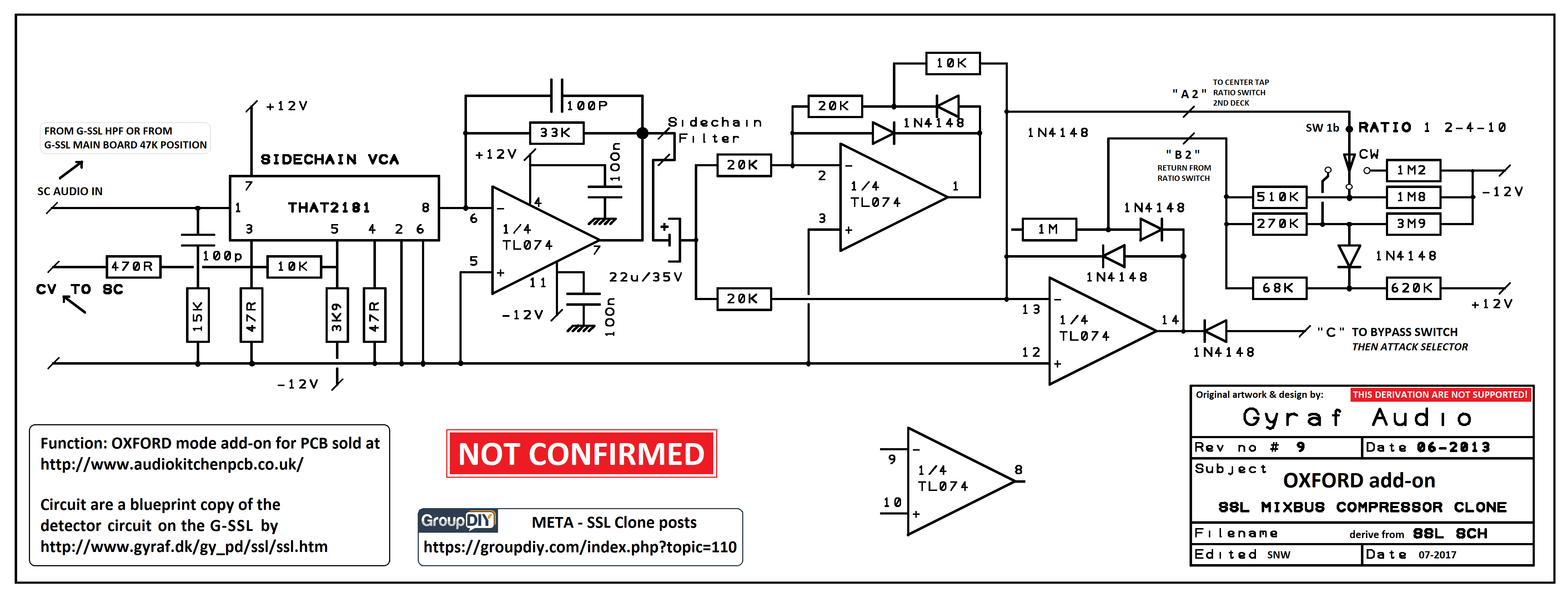
Funny thing are that some users find the original G-SSL misbehavior useful on some material and therefore implement the dual detection as an option with a swich.
Aarhus mode are sometimes used to describe the original G-SSL behaviour with a mono rectifier. Reason are that Jakob Erland (Gyraf Audio) are located in Aarhus, Denmark.
The G-SSL board has implemented a lot of the popular mods needed to better the design over the past decay. Why this dual rectifier option are not implemented puzzle me.
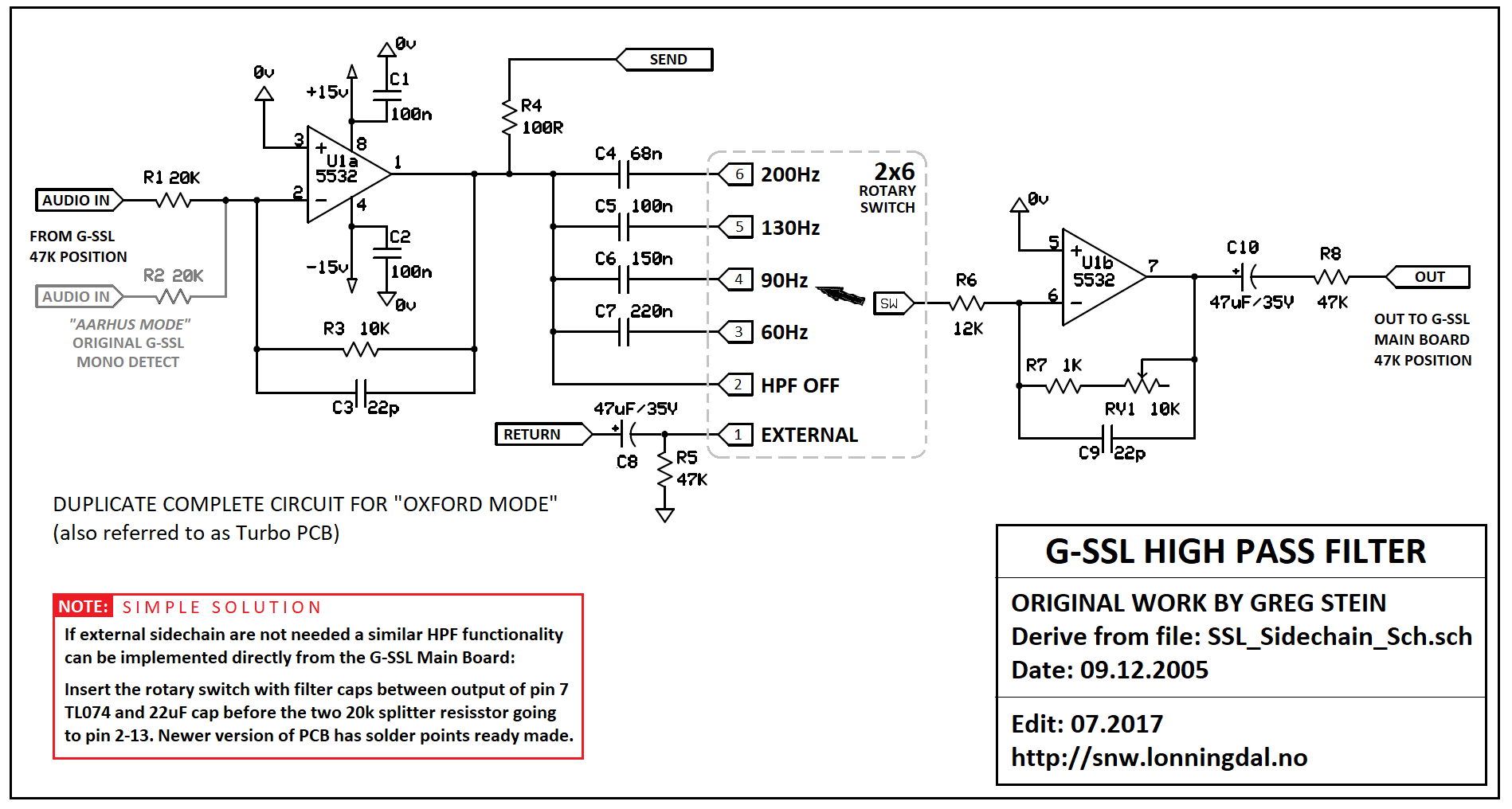
HPF - High Pass Filter
Popular function in many modern compressors are to implement HPF to lower the pumping originated from low frequencies. This filter is not in the actual audio path, only the detection circuit are affected.
Greg Stern published a nice version with buffers and option for external sidechain input.
Use impedance of 12k ohm (R) when calculating alternative filter caps for Greg Stern's HPF.
Many online RC filter calculators like you to input cap values in microfarads (uF).
1uF = 1000nF
We can simply divide nanofarad (nF) cap values by 1000 to get uF. A 220nF cap is therfore 220nF/1000=0.22uF
Remember, if Oxford mod are to be implemented we need two HPF filter setups regardless of which HPF solution are used.
A dual switch will therefore be necessary to select frequencies.
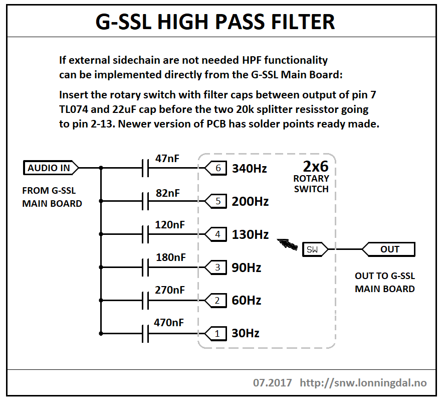
G-SSL PCBs from revision 11 now comes with soldering pads to insert a switch with a single or multiple caps in front of the rectifier op-amp. If external sidechain aren't needed this is the easiest way to implement HPF.
On older boards one can lift the 22uF blocking cap before the rectifie op-amps.
Use impedance of 10k ohm (R) when calculating these local RC filter caps for insert on the G-SSL main board. Fc = 1 / (2 * pi * R * C)
Exact cap values and quality are not critical as they are not in the actual audio path. As seen in the list we get very close to Greg Stern's useful frequencies with standard cap values.
G-SSL local RC filter cap values:

Theoretical values ≈ Standard values
------------------------------------
   79.5nF = 200Hz  ≈   82nF = 194Hz
  122.4nF = 130Hz  ≈  120nF = 133Hz
  176.8nF =  90Hz  ≈  180nF =  88Hz
  265.0nF =  60Hz  ≈  270nF =  59Hz

More standard values
------------------------------------
   33nF = 482Hz    |  150nF = 106Hz
   47nF = 339Hz    |  220nF =  72Hz
   68nF = 234Hz    |  330nF =  48Hz
   82nF = 194Hz    |  470nF =  34Hz
  100nF = 160Hz    |  680nF =  23Hz
CNC mod - Current Noise Correction
This mod are to lower noise from the power supply. A 10ohm resitor between multiple power filter cap pairs to create a steeper filter slope. Retrifier bridge are moved to the CNC board. G-SSL PCB from versjon 11 have implementet 1 stage filter, while the CNC board utlize 2 filter stages.
Perhaps will a more advanced power supply implementing shunt regulators be the ultimate power supply mod for the G-SSL to create that "blacken silent" hi-fi bufs talks about. If we where to mess with aditional PCB that is.
G-SSL rev 10 boards now have the 78L12/79L12 pair after the +/-15V regulators. This give less heat, but interestingly 78xx/79xx series supposedly give enhanced sound quality when in/out voltage difference are closer to 2V together with optimized load resistance. There are a lengthy discussion on diyAudio that I don't completly understand. But selecting the correct cap size on the regulator output depending on circuit load resistance seams to be a key to get these regulators linear and sound fine in audio circuits. Bigger and more caps are not the best way.
VU meter
Nah, I won't bother with this. Compression has to be set up by ear and the standard meter do show how many dB it compress, which is the main purpose of the device. I might look into a high resolution 0 to 3dB full scale LED meter to better learn how light compression touches the audio.
True Bypass
This we will do, mainly to ease patching on the two bus. At the moment I'm thinking on a operation mode switch to select between Oxford / Internal Bypass / G-SSL, and then have a dedicated True Bypass switch.
Class A DOA with Transformers
Replacing those cheap NE5532/34 op-amps on the input and output are very tempting. On the other hand they are somewhat neutral sounding and it might give more diversity for any studio to do this kind of color circuits in dedicated pre-amp style devices.
If I decide to go this route I will look into setting it up as a stereo mixer for internal parallel compression with a mix knob.
VCA
I’ve decided to do my build with THAT 2181 AL (0.01%) or BL (0.02%) THD trimming. To my understanding distortion in the detect circuit will not make much difference for the overall end result. Interestingly, Mouser stock all three trimming versions. Then for the price of four BL trimmed THAT2181 we can have two AL for the audio path and two CL trimmed (0.05%) for the detection circuit.
G-SSL PCB rev #9 had silkscreen resistor values changed to work with THAT 2181. There are aslo some resistor changes from rev #11.
The L here indicating 8 pin single-in-line (SIP) package. AS, BS and CS will be the surface mount SO packages.
 Mouser Part Numbers
 -------------------
 887-2181AL08-U
 887-2181BL08-U
 887-2181CL08-U
Left or Right / Stereo sense selector
This could be an easy modification. Have the compressor only react on audio from one channel might be useful on some material. It also makes for the unit to function as a mono unit with external sidechain.
Button count are rising. Maybe two push buttons for Left-Right. Or 3 way toggle with Stereo in center. Or combine with True Bypass rotary switch as TB/Stereo/Left/Right. Last sugestion not the most intuitive but save panel space .
Jakob Erland project page: http://www.gyraf.dk/gy_pd/ssl/ssl.htm
Great overview by Matt Fischer of resistor values to use http://diy.fischerworks.com/gssl_vca.shtml
Complete kit can be obtained at https://pcbgrinder.com
Add-on PCB’s, sadly without schematics are available at https://expataudio.myshopify.com
Comments
Your comment are welcome
Peter     2018-04-04 20:31:00
Hi. What sets the potentiometer RV1 10k in HPF??
Oyerockin    2018-03-25 08:35:04
Thank you. Gssl project so popular and so many modes are done, so it get harder and harded to find all the the info and you did put it all in one place. Great stuff!