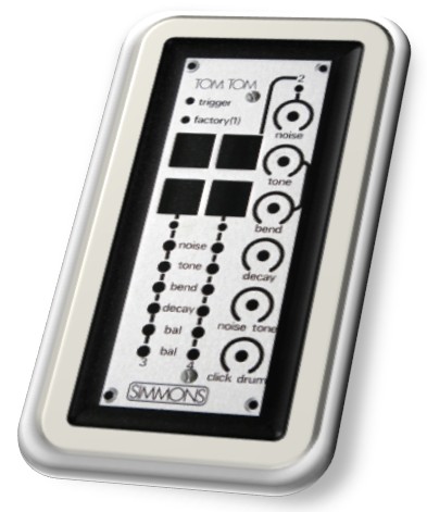
sds5/tom_panel_skewed.jpg
To view high resolution images, right click on image and select View image or Save image
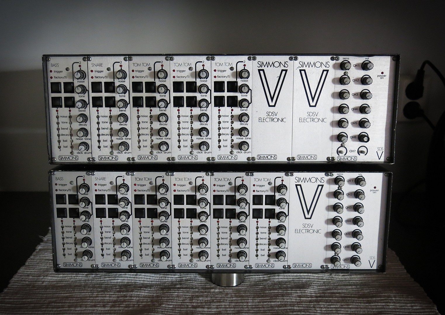
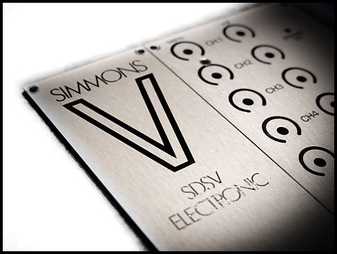 The V symbol / sign can have many meanings from sci-fi tv show logo to logical disjunction. In the context of electronic drums the V represent the roman numeral 5 in the series of Simmons Drum Synthesizer’s.
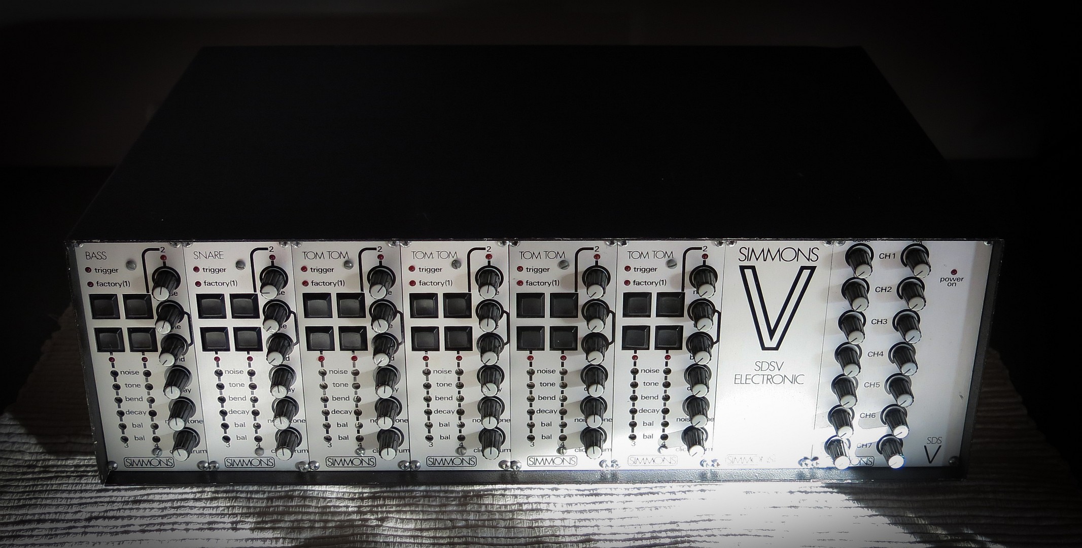
While electronic drum sounds had been available for more than a decade SDS V where the first complete drum kit available to let years of drum practice come to good use for the trained drummer. Meaning great drum grooves now could be had on recordings utilizing electronic drum sounds. Looking back on what actually become popular music in the 80’s when SDS V where in active service that might be disputed despite the long list of great drummers playing SDS V most of the beats where programmed. But at least the drum sounds from SDS V become enormously popular, and still are for some music genres.
Simmons signature tone, the falling pitch on the decay, the peew sound as it often is called is an important design feature but it is actually optionally. As many are pulled off by this sound it should be mentioned that users of analog Simmons gear are not locket into that sound universe alone, although many enjoy overdoing it. For the Tom channels this Bend function is also sensitive to strike force (trigger voltage) to simulate how the tensions of the drum head on an acoustic tom rises when hit harder, and then get lower when drum sound decays.
According to this wiki an ARP 2600 where used as reference when sketching out the block diagram for early analog Simmons synth engines. ARP 2600 where then and still are a very popular synthesizer for percussive sounds.
Each drum module utilize the SSM2044 4 pole (24dB) Low Pass Filter chip. This well reputation filter are known from Drumulator, SP-12, SP-1200, Emulator 1, Polysix Trident, MonoPoly, PPG Wave 2.2, 2.3, Bit01 and more. Seeing all those famous E-Mu drum machines using this filter is no coincidence as this filter were originally designed by Dave Rossum, one of E-Mu's founders.
SSM2044 have been out of production and stock for many years and no doubt a few SDS V modules have been sacrificed as donor for more popular and rare synthesizers. Luckily there now are a reissue on offer from Sound Semiconductor named SSM2144.
With the filter chip in production again there is nothing stopping Simmons to enter the modular eurorack marked with it brand name and genuine analog drum sound. Although users here probably want more than a plain trigger source now custom to modulate every aspects of their modules from voltage sources.
How custom synth chips simplified the design of the SDS series synth engine can be seen from where SDS 3 and SDS 4 used Moog’s famous ladder filter (in style of the patent infracted ARP 4035 filter module to the SDS 5’s SSM2044 4-pole and later SDS 7 and SDS 8 having even more of the synth engine in a single CEM3372 chip.
An interesting aspect here are the speed of development done by Simmons. All these models where released over a five year period. Looking at how long electronic drum products from Roland and others are in circulation these days one might wonder if the world now stand still with regards to this kind of instruments.
The volume controls on the right hand mix channel affect only the mix output. They have no effect on the individual channel outputs or the right and left outputs. Thus a drummer can mix his own monitor level on stage leaving the main channel outputs to the P.A. unnaffected by level changes he may make on stage.SDS V User Manual
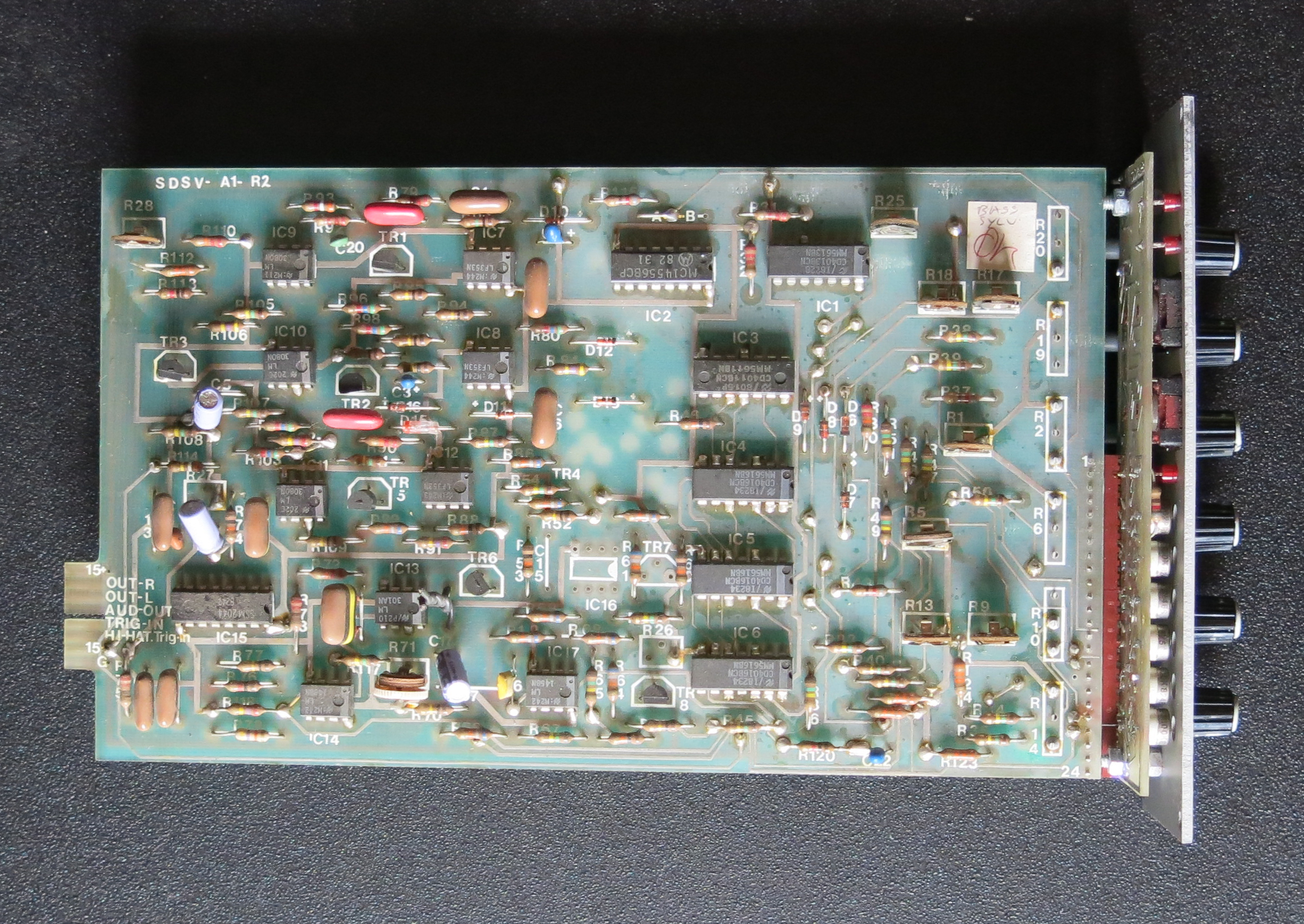
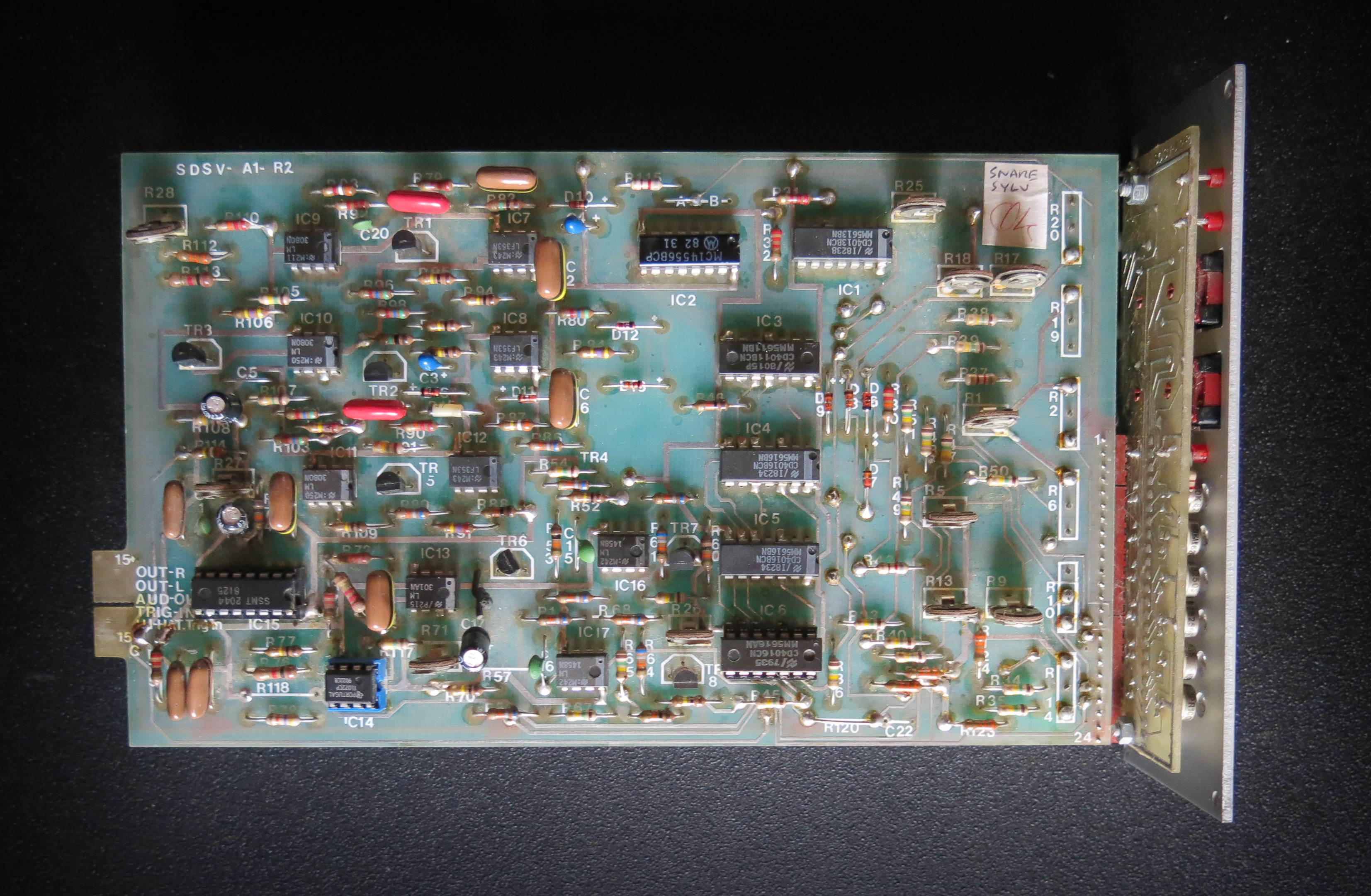
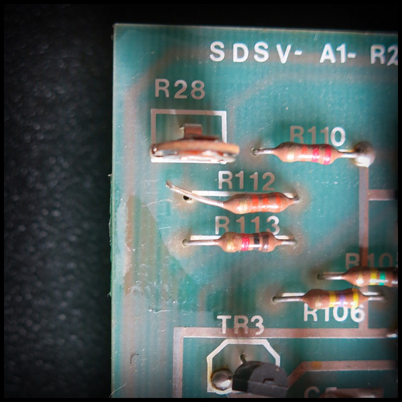 There is a little trick one can do to minimize channel count needed for SDS V. Lets say we only need to have the bass drum on a separate out and the rest of the channels on the stereo bus. For a setup like this it would be nice to mute the bass drum from the stereo bus. On the module PCB we find the variable resistor R28 in the upper left corner. This is the balance potentiometer for the stereo out on each of the sound modules. By desolder and lift up one leg of R112 going into the R28 center pin we disconect the module from the stereo bus.
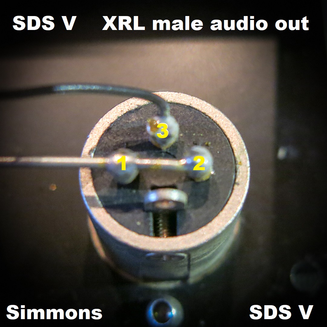
Despite SDS V has loads of XRL connectors on the back none of them are actually running balanced audio. They were used mostly course they were ‘pro’, - regarded more robust and had locking mechanism.
If one buy new XRL to mono TS cables one are likely to run into problems course the SDS V audio outputs are wired according to vintage American standard.
    Pin 1 (chassis ground) Ground
    Pin 2 (cold)           Ground
    Pin 3 Hot              Signal
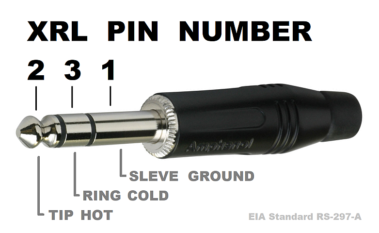
New cables following EIA Standard RS-297-A will have
    Pin 1 (ground)
    Pin 3 (cold)
    Pin 2 (hot)

    TRS plugg (stereo): Tip (hot), Ring (cold), Sleve (ground)
    TS  plugg (mono):   Tip (hot), Sleve (cold and ground)
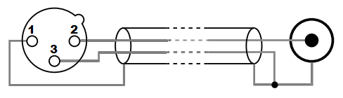 Original SDS V audio out with a new standard mono XRL to TS (or RCA) cable will then work out to something like this: Pin 1 (ground) and Pin 3 (hot) both goes to Sleve (ground), Pin 2 (cold) goes to TIP which results in no sound as signal on Pin 3 are shorted to ground and ground also goes to Tip.
XRL to TRS cable into a balanced input should result in sound where hot from SDS V goes to the Ring (cold). But into a unbalanced input the Ring on the TRS coming from XRL Pin 3 often find its way to ground and thereby short out the sound. In some unbalanced input jacks the Ring are left unconnected which also result in no sound.
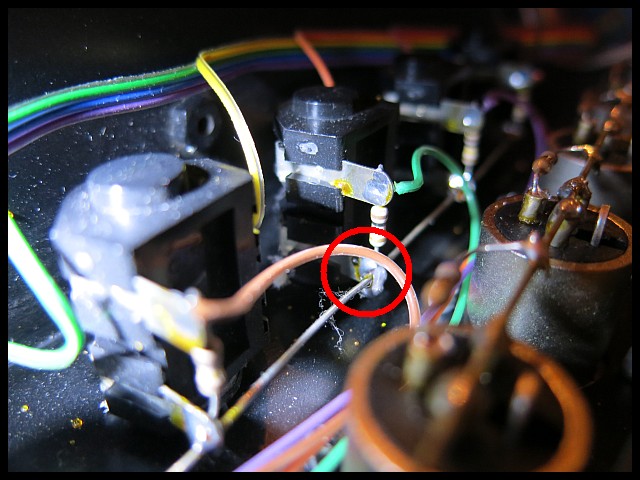
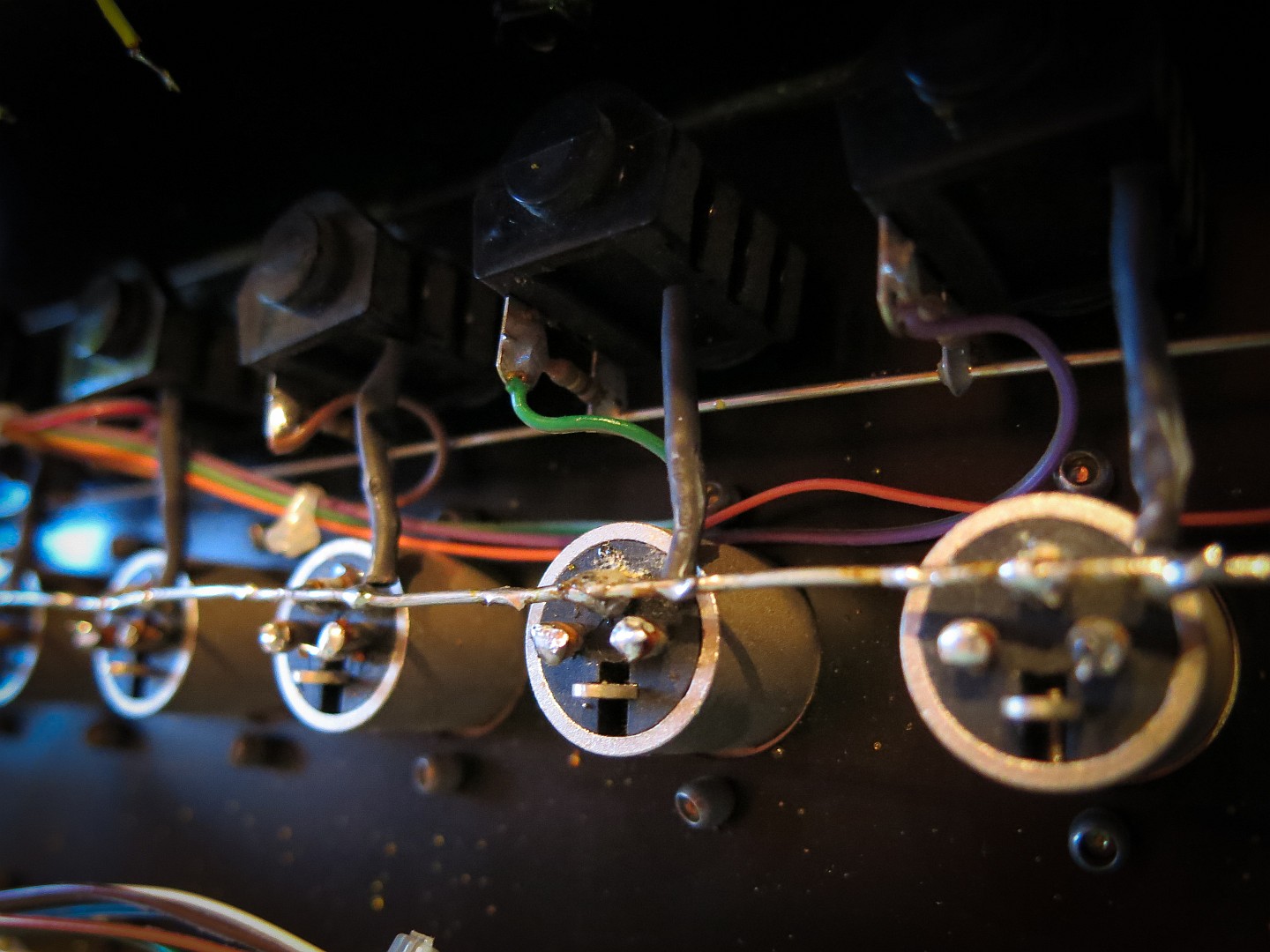 While this can be worked around making custom cables fixing this issue permanently at the problem source, inside the SDS V back panel is actually a much easier soldering job. As seen in the images I decided to move the ground wire to Pin 3 and disconnect the 68 ohm shunt resistors on channel outputs.
While we have the back panel disassembled there is another peculiarity we can sort out. From the service manual we read...
The separate outputs Channel 1 to 7 are low impedance, low level microphone outputs, whereas the mix right and left outputs are at line level. The individual outputs can be converted to line level if required by removing the 68 ohm resistor on the back of the channel output sockets. Simmons SDS V Service Manual
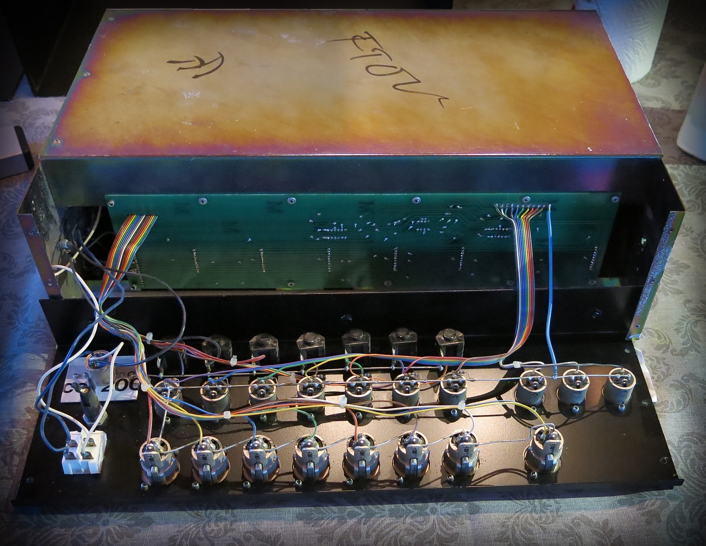
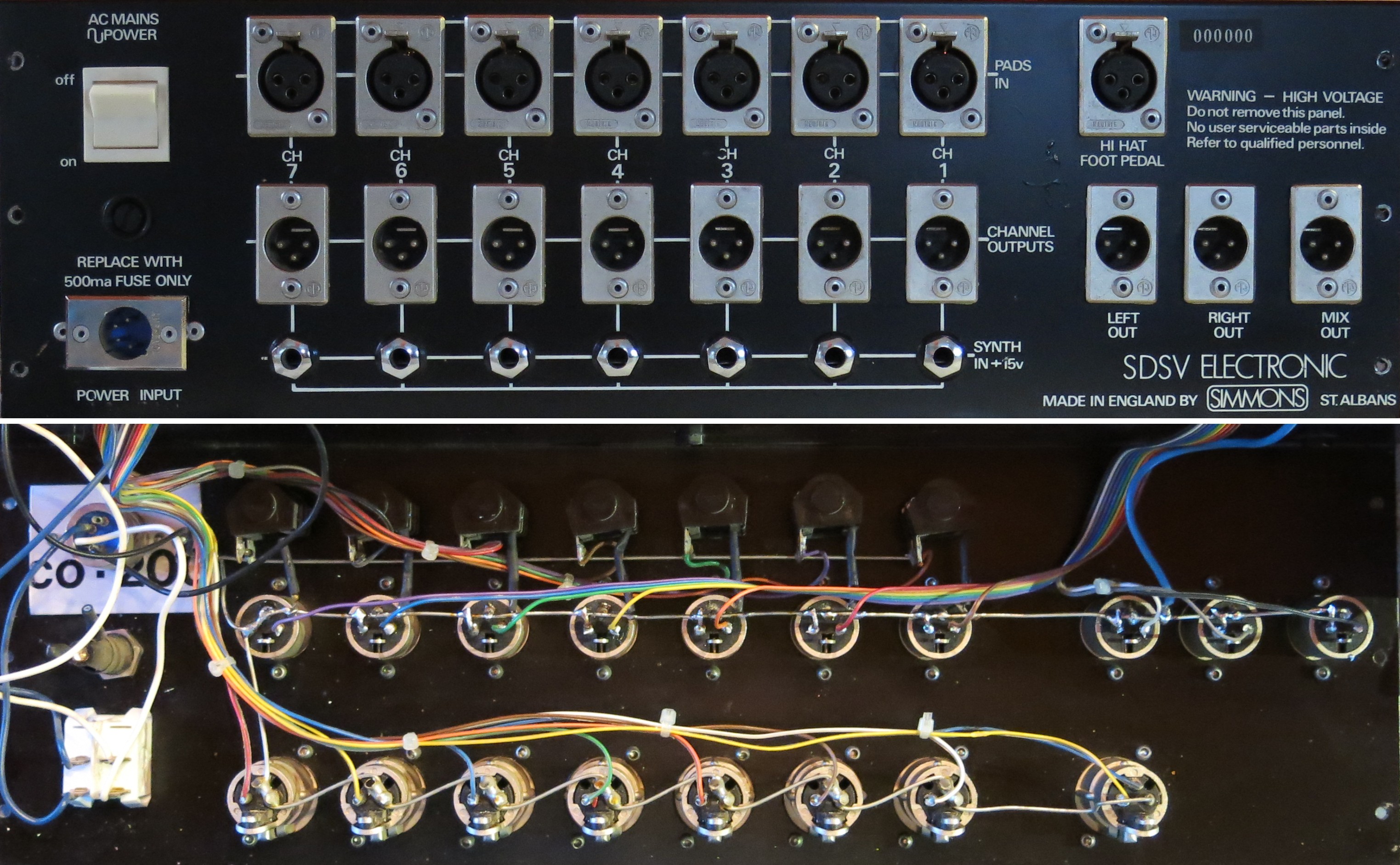 Image above show SDS V back panel with the following modifications:
- Output moved from Pin 3 to Pin 2 to comply with standard XRL connection
- 68 ohm resistor lifted from output for line level output (isloated and left on the ground bus)
- External dual transformer. Not sure as to why but we can speculate? If this has been a touring instrument multi voltage toroidal transformer might been a problem to source within a given time frame. This will explain why the external PSU where so clearly marked with handwritten voltage label. The external PSU is just as simple as the SDS V with 7815/7915 voltage regulators but has 115/230 primary windings. Or maybe a previous owner had problem with hum. The internal transformer is placed very close to the mixer PCB traces.
Another tempting modification would be a 25 pin D-sub connector for quick and tidy audio setup with all 7 channels and the mono MIX. Probably less interesting if only 5 channels are populated, unless free channels where modified to have audio inputs for mixing purposes.
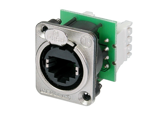
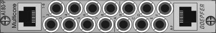
A multi connector for triggers using shielded RJ45 network cable compatible with Doepfer A-180-9 pinouts would be a nice feature.
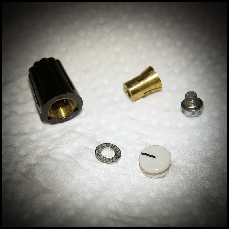
With precise lathe and molding these Cliff knobs doesn't come cheap. But 36 years down the road they still clean up nicely and looks almost like new. For some reason these knobs seems to be allergic to their caps. You rarely see a SDS V complete with all its caps in place.
Thanks to Ed Rose in USA who stock these parts it is possible to make the SDS V look nice again. You can reach Ed through his gmail account, the Simmons list on Yahoo or send a private message in the comment section here and we can set you in contact.
 Input would work after some jack rattling. Tuned out the soldering point on the ground bus had loosen due to stress course the nut on the jack connector where loose.
 Inserting modules can sometimes be troublesome, at least if the chassis is full and one can’t support the card at the connector end. Setting the chassis on its back with the front opening upwards simplifies this task considerable.

Porotype from 1979 and first introduced 1980 under Musicaid which folded the same year. Commercially available from 1981 with the Simmons brand. Replaced by SDS 8 with SDS 7 as flagship in 1983.
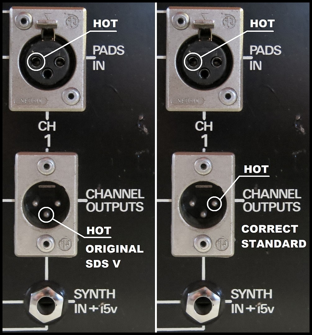 When looking at the back of SDS V Pin 1 and Pin 2 in the XRL connector will be opposite of each other depending on gender. Male (audio out) Pin 2 are the right pin. For the female connector (PAD input) Pin 2 are the left pin. And to clarify, Pin 3 is center on both genders. SDS V PAD inputs has correctly Pin 2 hot (left pin).
| Pads | Sequencer | |
|---|---|---|
| Max output at | 0.075 Volt | 7 Volt |
| Minimum input | 0.005 Volt | 1 Volt |
| Maximum input | 1.5 Volt | 15 Volt |
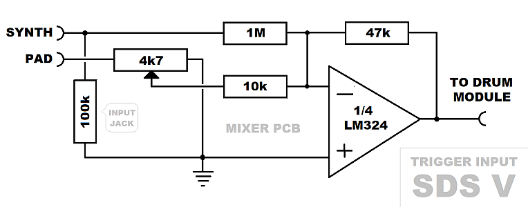
| Impedance | 4k7 ohm | 1M ohm |
| Beside drum volume the trigger voltage also alter Noise Pitch for Bass/Toms and Bend for Toms. | ||
| Control | Internal VR |
|---|---|
| Noise Pitch | R18 |
| Tone Pitch | R17 |
| Bend | R1 |
| Decay | R5 |
| Click Balance | R13 |
| Noise/Tone Balance | R9 |
| Left/Right Balance | R28 |
| Filter Q (resonance) | R27 |
| Filter (Dynamic Sweep) | R25 |
| Noise generator gain | R71 |
| Snare Osc modulation depth | R26 |
| See service manual for factory settings (visual approximations only) | |
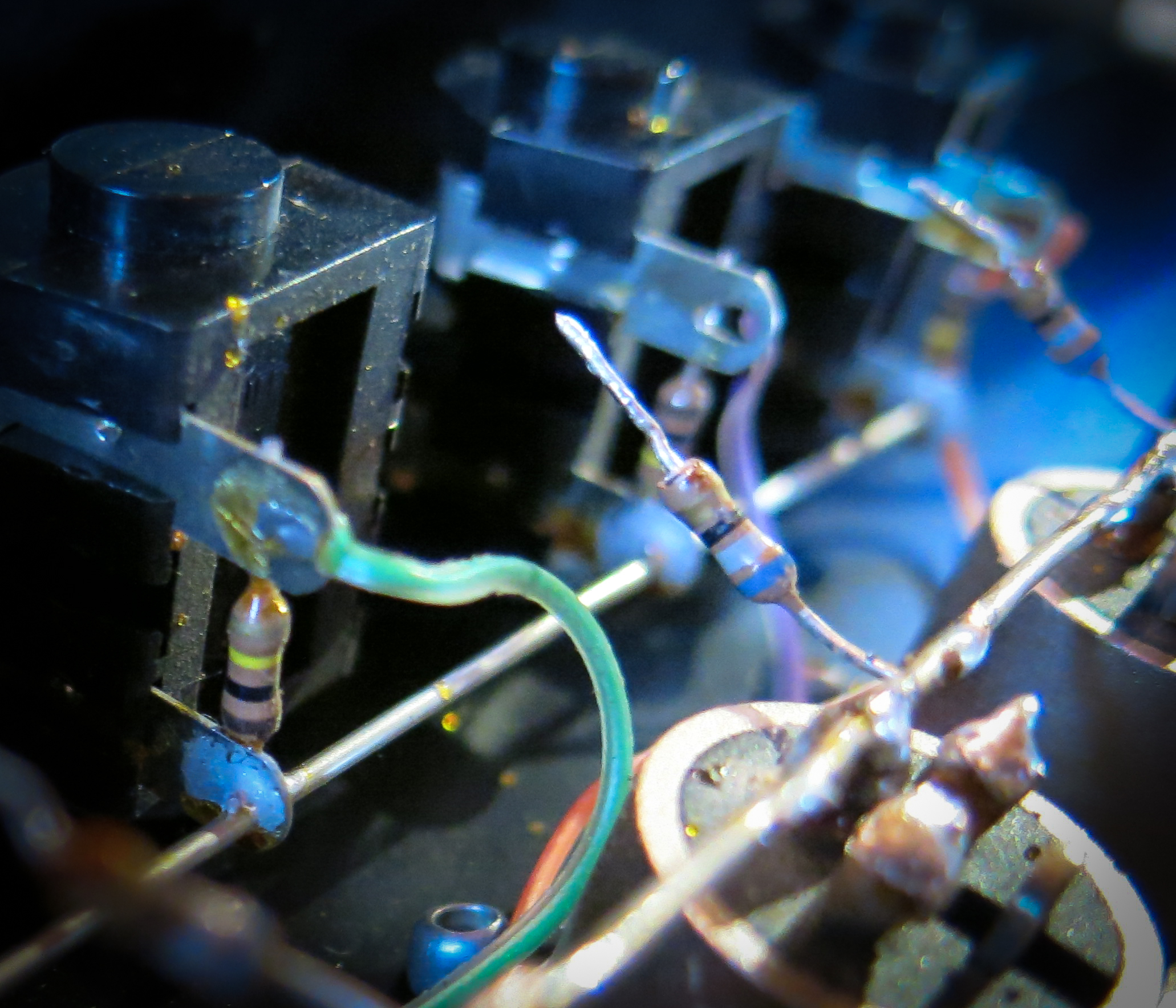 Disconnected 68ohm shunt resistor left hanging on the ground bus. Will be isolated later on.
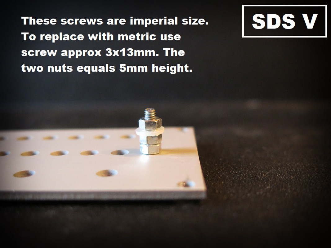
 To remove back plate first remove bottom plate including the feets. Then remove the 6 screws on the back plate.
Suggested list prices Januar 1983
Simmons Group Center USA

Simmons SDS V RACK no modules	$ 852.50
BASS DRIM MODULE		$ 387.50
SNARE DRUM MODULE		$ 387.50
TOM-TOM MODULES 		$ 387.50
DIGITAL HI-HAT MODULE		$ 496.00
DIGITAL CYMBAL MODULE		$ 496.00
BASS DRUM PAD			$ 232.50
DRUM PADS (small)		$ 170.00
STEREO CYMBAL BAD		$ 170.50
HI-HAT PEDAL			$  85.25

5 piece kit no hh/cymbal/stand)	$3780.00

SDS-6 SEQUENCER			$2800.00

CLAPTRAP			$ 255.00
Wolfgang bloged http://blog.simmonsmuseum.com a link to this little gem. Wolfgang’s site is the place to go to learn about Simmons pads and history of Simmons products.
 https://en.wikipedia.org/wiki/Hexagon
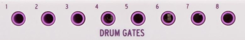
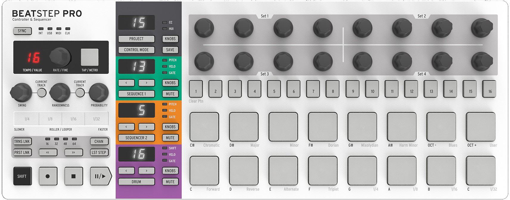
An interesting partner with the SDS V module is the Beatstep Pro sequencer. Its 8 dedicated drum gates makes for easy connection and turn any analog SDS drum unit to a great sounding 'drum machine'.
Wolfgang at Simmons Museum talks with Richard James Burgess about the SDS V prototype http://blog.simmonsmuseum.com/?p=585
Synthjack's DIY SDS-V voice https://syntherjack.net/sdsv-voice-board/
Synthjack's DIY SDS-V Digital add-on https://syntherjack.net/sdsv-hihat-expander/
Synthjack also have an Analog Clap Trap clone https://syntherjack.net/snapclap-the-only-handclap-you-need/
sds5/tom_panel_skewed.jpg
To view high resolution images, right click on image and select View image or Save image
Select file from list below
Your comment are welcome
Ed Rose    2020-02-06 18:09:24
Two caveats when using BeatStep Pro Drum Gates with any Simmons module:
1. BSP records the note length, too, which, unless you have the fastest fingers in the world, will be way too long to accurately trigger SDSV, SDS7, etc.. So, once you record a track on BSP you need to go back and adjust all the Note Lengths down to their minimum for your Simmons module to trigger correctly. Otherwise, the longer gate lengths will result in VCAs being held open way longer than they should and the sound will not be the classic 'Simmons Sound.'
2. BSP Drum Gates are not dynamic - they only output 10v signals. Which is a shame considering how well SDSV and SDS7 respond to dynamics.
anonymous    2020-02-02 01:00:11
Thanks Jarry

Ed Rose — The Simmons Guy migh be the man to help you. He has a website with the same name ending with .com

best of luck
Hans
anonymous    2020-02-02 00:47:36
Hi, thank you very much for your page about Simmons sdsv.  Great.  I'm a big fan of this device.  I have some pieces at home, too.  Now I'm going to repair.  Your information helps me very much.  But I can't find one.  I have modules with broken buttons.  Do you know where I can find an original, or at least some replacement, please?  Thank you very much for your answer.  Sincerely, Jarry
YUJI MAKINO    2019-05-19 23:31:09
Hello!
From Japan
I like simmons SDS-5 sound !!

These ontents are good!!