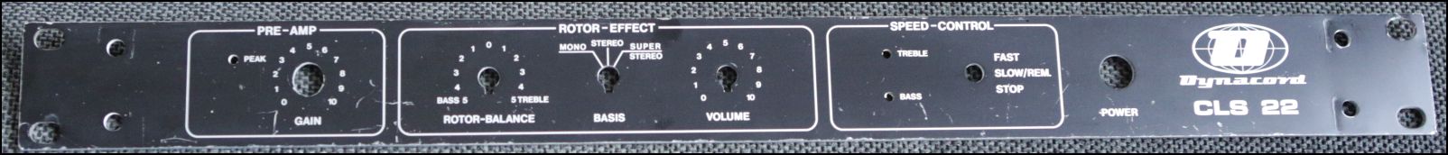
.png)
cls22/Dynacord%20CLS-22%20service%20(6).png
To view high resolution images, right click on image and select View image or Save image
CLS 22 is the predecessor to the more known CLS 222. They have identical effect circuits except CLS 222 has an extra position for the stereo spread plus effect bypass. Not true bypass though, leaving the pre-amp and output driver in circuit — still colloring audio signal with three RC4136 / RC4558 op-amp stages and lowpass filtering.
Component values for both the additional position and the original stereo spread has changed in CLS 222 — which makes the Stereo setting on CLS 22 unique. Mono and Super Stereo settings are identical for both units thought.
Original stereo mix in CLS 22 is done with R202/22k and R203/5k6.
The new 4 position switch implementation in CLS 222 is done with R202/39k and R203/2k7 where the new position use resistors R213/56k and R220/6k8.
To suppress speaker pops CLS 222 mute all three outputs at power-on using a relay. This delay circuit has its own dedicated power supply utilizing separate secondary windings on the main transformer. As the older CLS 22 actually use an identical transformer modell it should be possible to replicate this mute circuit on a separate PCB if so desired.
CLS 222 have a dedicated mono output with its own buffer amp. Signal is summed from the stereo out after the stereo output amps and volume control and have seperate pins on the power-on mute relay.
CLS 222 also seems to have double the capacity from 10uF used in CLS 22 to 22uF for all the power filter caps spread around the PCB board. Possible lowering the noise floor.
CLS 222 added trimmers and service switches around the tweeter/bass rotor balance potentiometer making it possible to calibrate center position for this user control.
There are some weight difference between these siblings as CLS 222 favour thin aluminium sheets for top and bottom plates whereas CLS 22 here have thick and heavy steel plates.
Note that none of the jacks or XRL on either units actually run balanced audio signals. User can choose to connect with the most convenient of them as jacks and XRL run identical signals. Mono out on the CLS 222 has it cable driver after the volume potentiometer — making this output impedance constant independent of volume setting.
Bought my first CLS 22 as non functional knowing it blew a fuse immediately when powering on. When delivered I learned it been heavily used and transported in a case with other gears without proper rack protection. Resulting in bent panel and potentiometer axles, missing knobs and with loads of surface scratches all over the chassie and panel.
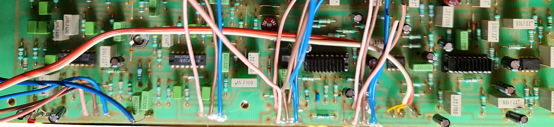
Electronic problem where a faulty tantalum capacitor shorting the power rail which then burned out the B80C800G1 bridge rectifier. There are lots of these tantalum spread around the board and I decided to replace them all with better Panasonic electrolytics to ensure none of the many obsolete and rare chips suffers like this rectifier.
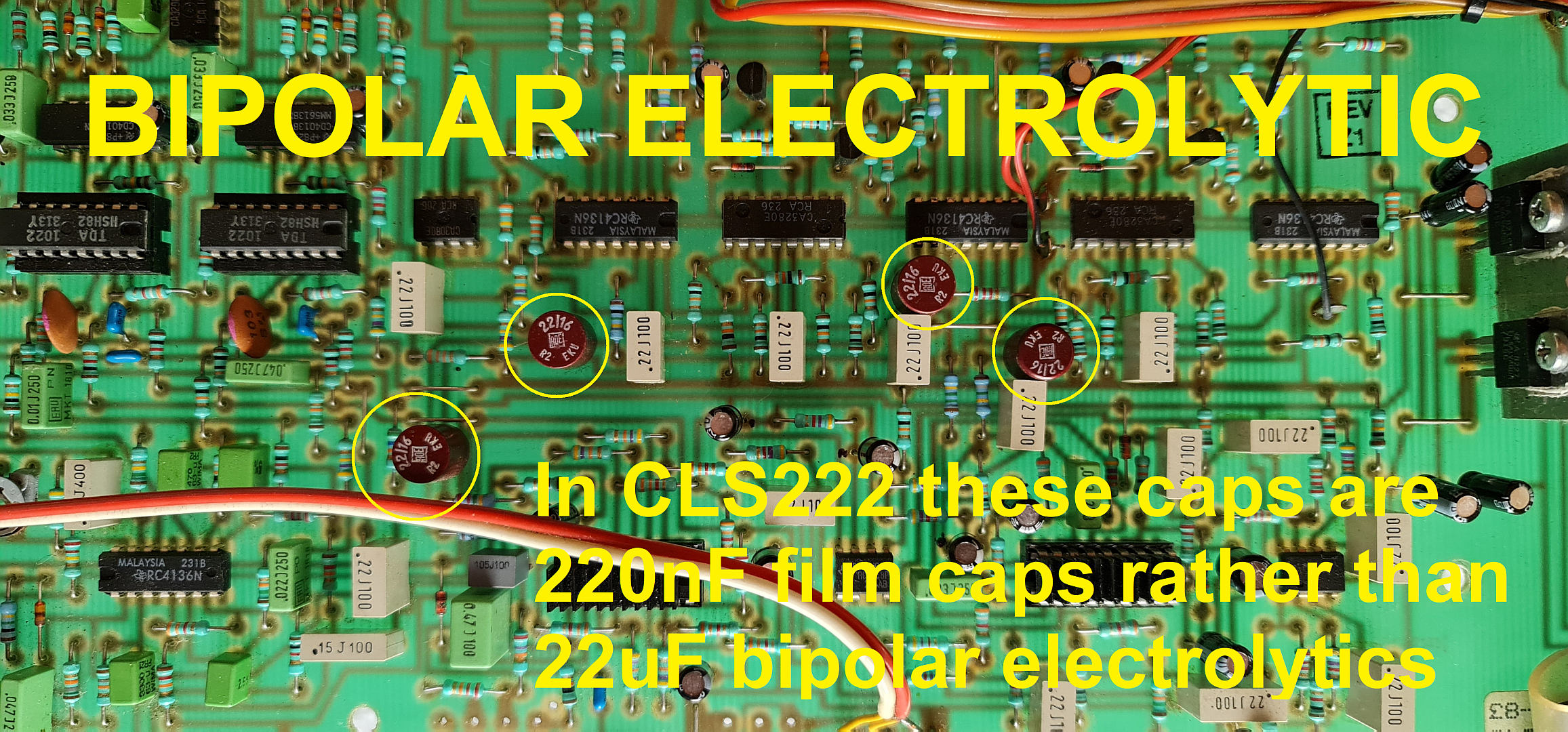
CLS 22 make use of four bipolar 22uF electrolytic caps in position C108, C109, C110 and C111. This might have been an early print or reading error at Dynacord with a missing dot punctation as the later CLS 222 for these capacitor postitions have 0.22uF (220nF) film caps with no other changes to the circuit impedance.
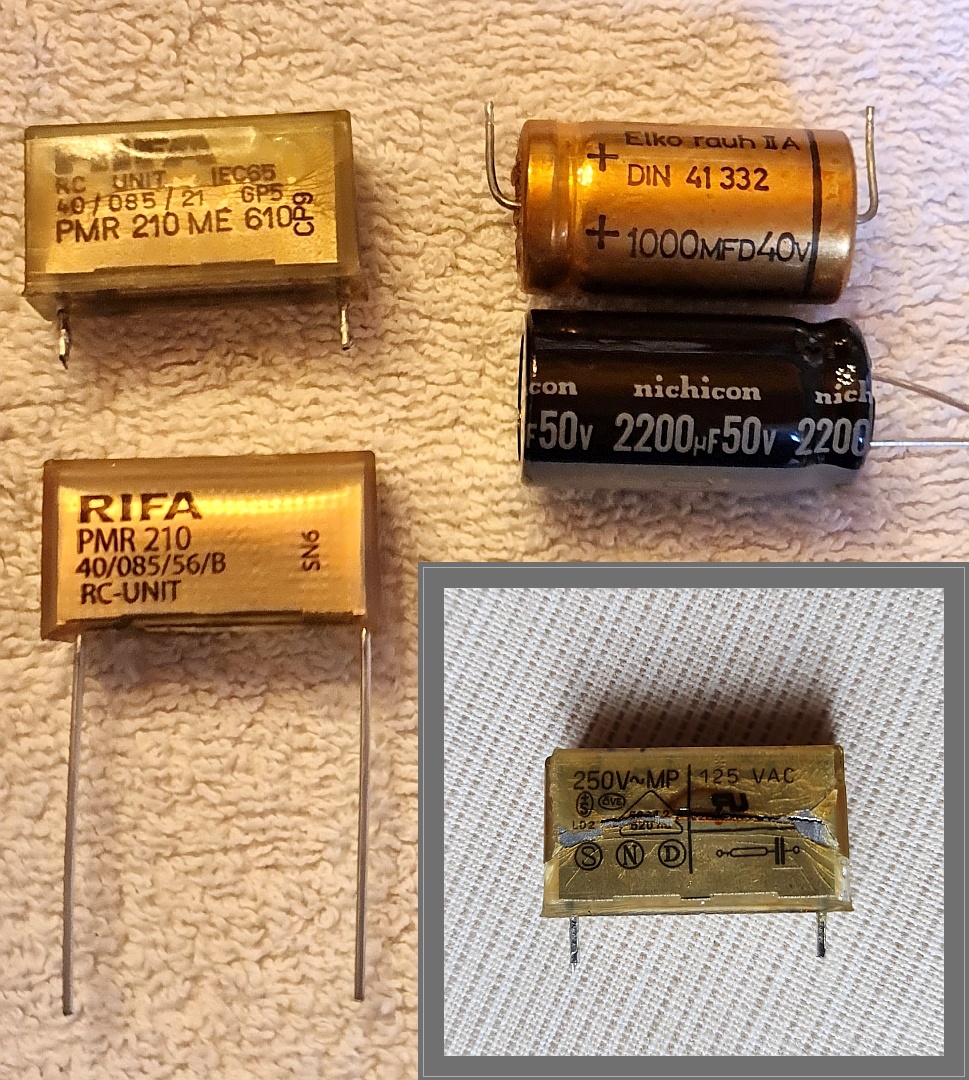 If you can't find replacement part for the nearly 40 year old Rifa (now Kemet) PMR210ME6100M100R30 I suggest you at least remove this 100 ohm / 0.1uF RC network from the mains as it will let out smoke with a nasty odour if it not already have done so.
Do not make this part yourself — unless you know what you're doing. It is ment to have special designed components that do not short and ignite when they fail. Schematics has this filter before the power switch but actually it is after. When this is re-written 06/2022 Mouser still have them in stock.
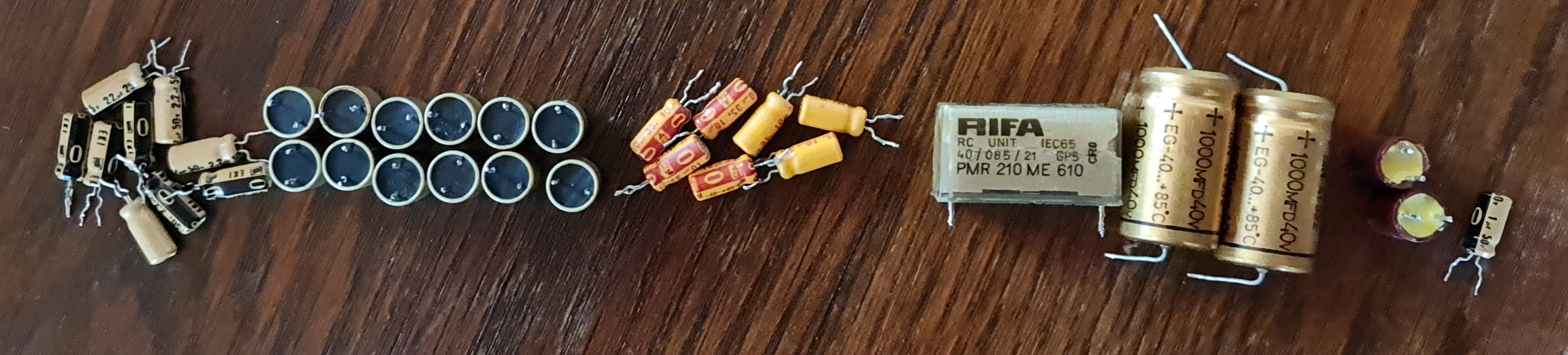
Nearly all 34 capacitors needed for a full CLS 22 recap-job have 5 mm spacing. Exceptions are main psu filter caps and the RC filter on the mains voltage. Values are 1uF, 2.2uF, 10uF, 22uF, 1000uF.
For CLS 222 there are a total of 21 electrolytic caps. 1x 1uF, 9x 2.2uF, 7x 10uF, 2x 47uF, 2x 1000uF + the RC filter.
CLS 22 sadly do not have silk screen printing on the PCB as the later CLS 222. For service purposes this makes it much harder to troubleshoot.
Both models have high quality PCBs and luckely no problem with pads loosening from the fiberglass when serviced as often seen in asian counterparts from this time period.
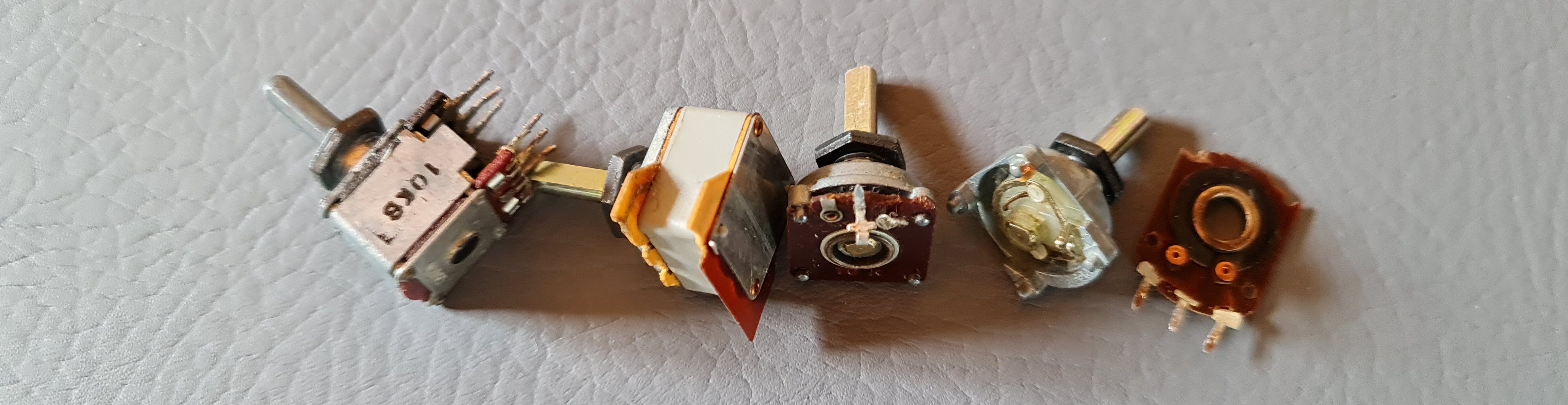
All original panel controls have 4 mm axles. This dimmenton not being very common for nearly three decades potentiometer and rotary switch replacement are often done using standard 6 mm axles which makes it common to find old Dynacord effects with a mix of different knob styles. Also original knobs used on these devices share the same problem as vintage Simmons products, — where the caps for some reason come loose and disappear.
16 mm and 9 mm pots with 6 mm axle can readily be found with same 7 mm mounting hole dimension as the original, — typical modern pots with M7x0.75 nut.
 When replacing pots and rotary switch consider using wire leads to PCB rather than strive to find parts that fits on the PCB. As front panel actually use these parts to build up rigidity result are that these parts with their soldering joints become stressed as the picture of defect parts show the result from.
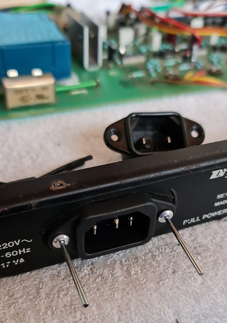 2 pin power socket replaced with 3 pin IEC socket with ground wire to chassis ground on back panel. Beside making the unit safer in use we now have the comfort of using modern standard IEC power cable. Of course with the added danger of ground loops. Didn't bother with a switch for ground lift as I've needed to use one on my setup.
Every tantalum replaced with electrolytic except one single 1uF tantal where a film cap took its place.
First pair of filter caps upped from 1000uF to 2200uF having identical size 16 x 31.5 mm. Also replaced some 10uF with 22uF as seen in CLS 222 (note some of the 10uF caps on the board are used for decoupling and no benefit to be had altering values for these).
Playing with the idea to move the Treble and Bass Speed trimmers to the front panel.
Possible mod could be to replace resistors for stereo spread with trimmers and then adjust to optimum setting.
True bypass with optional foot control might be useful.
Treble rotor:
R105 2M7: ramp up time
R201 1M2: ramp down time
C001 2,2uF: ramp up&down time
R193 + R195 + R039: final speed
Bass rotor:
R031 4M7 + R192 4M7: ramp up time
R030 6M8: ramp down time
C002 2,2uF: ramp up&down time
R194 + R196 + R023: final speed
This design started as a DIY project. The project grew step by step by comparison to the original Leslie cabinet.
At that time I had some experience with bucket brigade delays, flangers and chorusses. Most of the chorusses at that time worked unsatisfactory, i.e. delay did not sound "round".
I discovered the reason for that was using VCOs for clock modulation.
This yields in voltage-proportional frequency. With bigger modulation depth, the resulting delay variation becomes unssymmetric, simply because delay is proportional to 1/frequency. Thus I decided to build voltage controlled period generators as top frequency oscillators. With that concept the delay modulation yields perfect round sounding flanger/chorus/leslie effect.
Next aspect was loudness modulation. Specially the treble unit produces a angle-dependend acoustic level with a sharp maximum in the direction to the listener. Additionally, there is a smaller maximum due to reflection at the rear wall of the cabinet.
Switching motors works totally asynchrone for treble und bass unit, with a much slower response on the bass unit.All in all there is not one single secret behind it, but a lot of details I worked out in a period of one year. Circuitry was designed from scratch, there was no relevant information available for me besides the data sheet of the chip. And there were no products on the market at that time that gave me inspiration for the work.
The deal with Dynacord came later, when the first prototype was working completely. Like so often, this happened accidentally. I did some jobs in a commercial dance band, and their leader was a representative of Dynacord....
User voltwide from diyAudio
cls22/Dynacord%20CLS-22%20service%20(6).png
To view high resolution images, right click on image and select View image or Save image
Select file from list below
Your comment are welcome