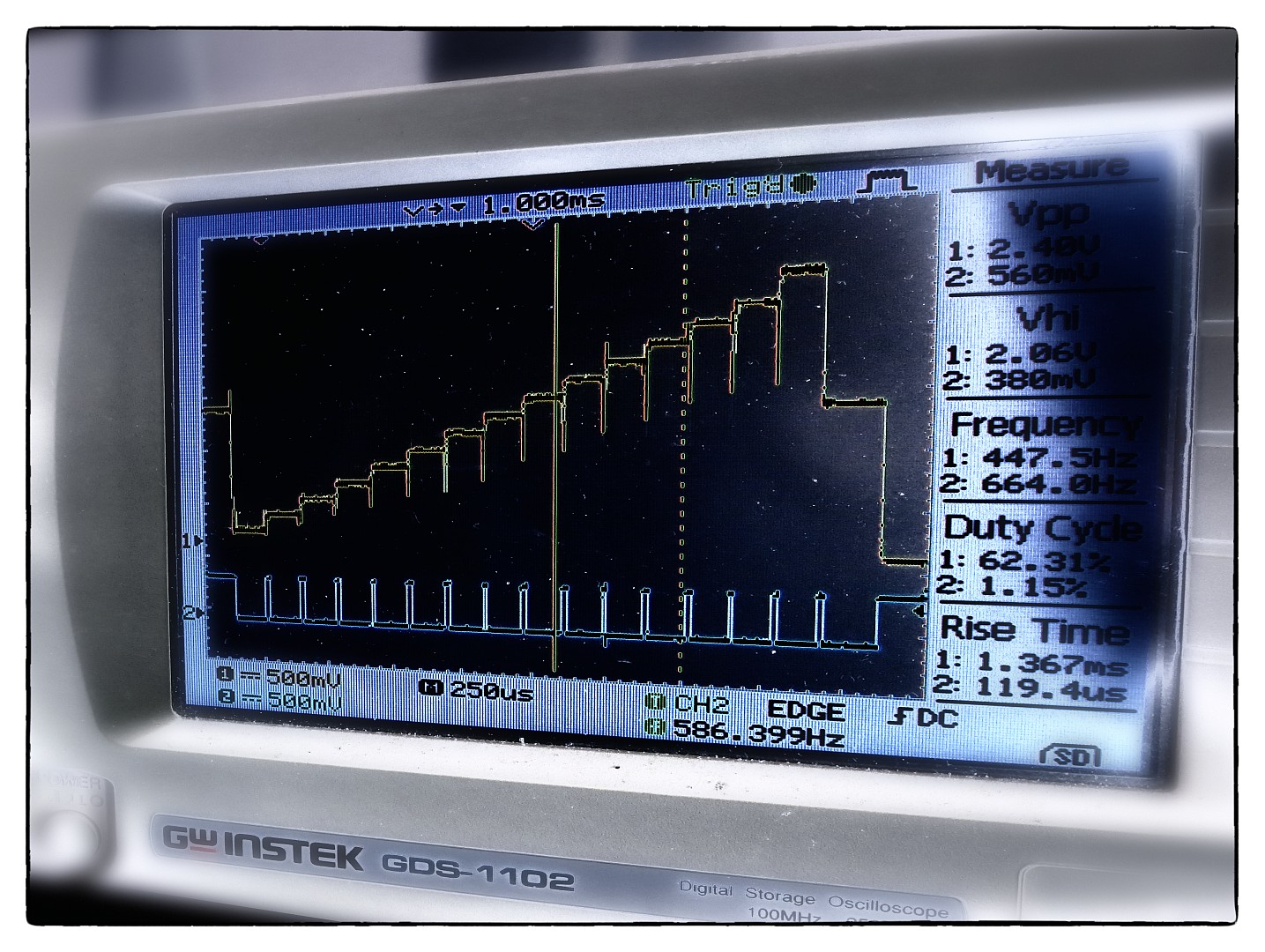
 SDS7 control voltage programmed to equal intervals
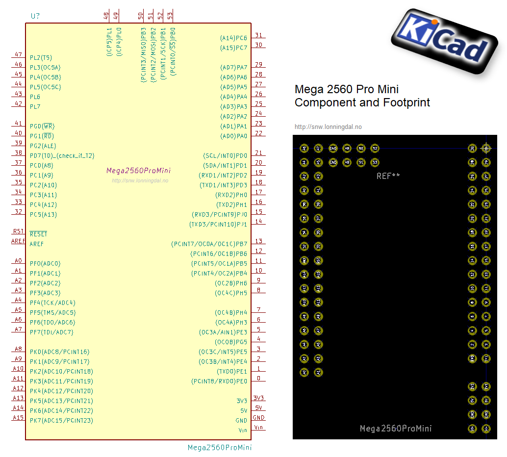

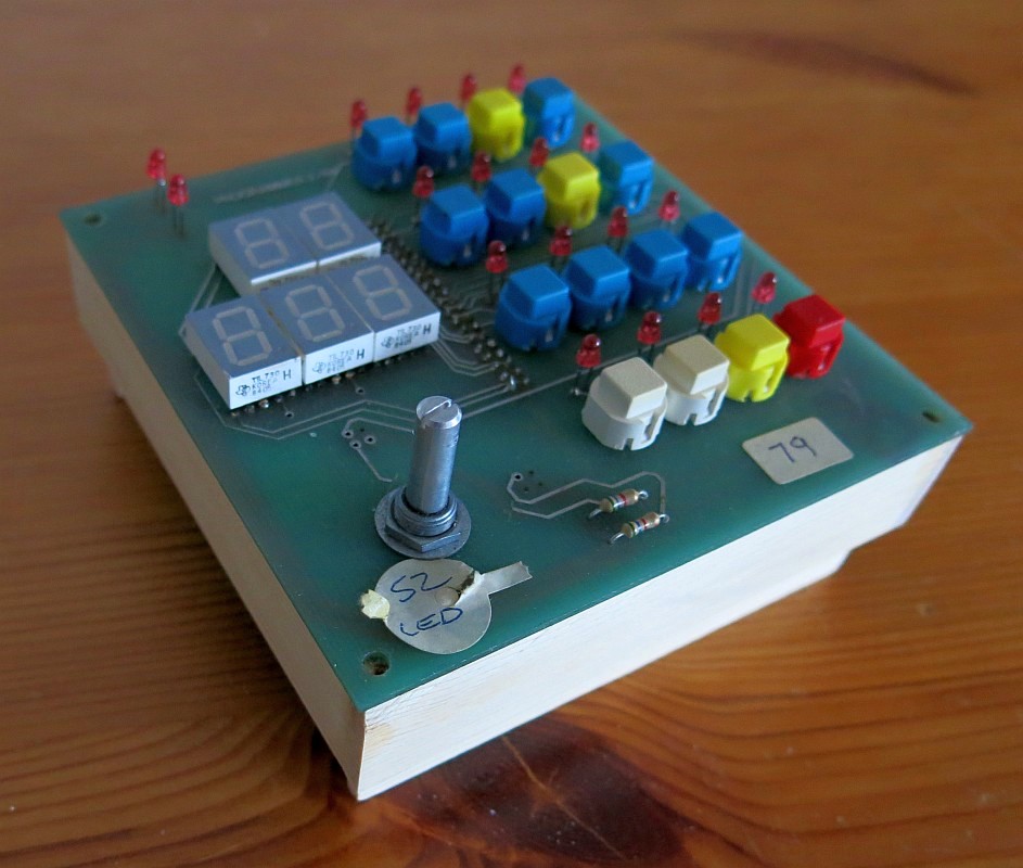
sds7mc/proto4.jpg
To view high resolution images, right click on image and select View image or Save image
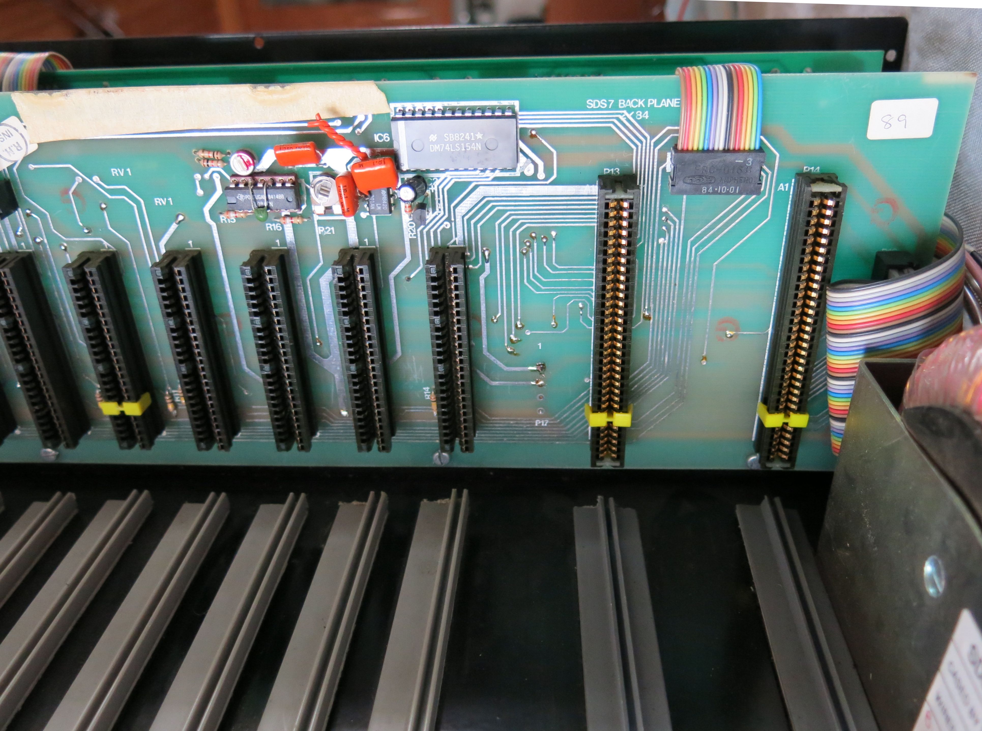
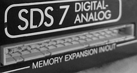
This wonderful vintage analog drum sound source have gotten a bad reputation over the years due to some stability issues. One of them being loss of memory where all presets are lost with unknown cause. There has been speculation if contact problems on edge connectors for the CPU and / or Memory boards can be one source for this problem. It could also be timing issues in firmware handling memory refreshes and updates poorly or even layout of PCB tracks or cable to the RAM cartridge on the back picking up interference and noise.
When the idea to try and have MIDI sneak inside the SDS 7 it quickly become clear there is no point trying to intermediate a control and memory management system already having stability problems. A completely new controller and memory board had to take control of the SDS 7 guts.
When first flying ideas for this project it where tempting to replace the control panel with an OLED display and 16 rotary controls for quick access to all sound parameters and drum kits. Then realizing a vintage instrument probably should be treated with more respect. Already experimented with wireless control and web-socket on other synth controllers and found it has limited usefulness decision where made to do SDS 7 modification in a more traditional fashion. Any fancy direct control will be done remotely over MIDI. This project attempt to be non destructive, it will preserve the vintage look and made to easily let the SDS 7 be reversed to original condition.
A lot of time where spent investigating if one of the latest 3.3V developer boards could be used. Very eager to have support for USB Class Compliant MIDI the Teensy 3.6 where scrutinized. Although possible it turns out that necessary level shifting to drive 5V circuit reliable, and with the large numbers of LED current drivers needed complicated the project with high parts count.
Decision to go with ATmel2560 are due to it's high pin count with 5V, capable to sink or source a LED directly. Project can be realized in a way that allows for a more powerful SoC be implemented later on where the ATmel2560 then only function as I2C slave (with the wire library) — or pass though device simply driving user-panel and do level shifting of address lines.
Schematics are done with KiCad, a cross platform and open source electronics design automation suite.
Custom SDS7 Library and Footprints sds7lib_r1.02.zip
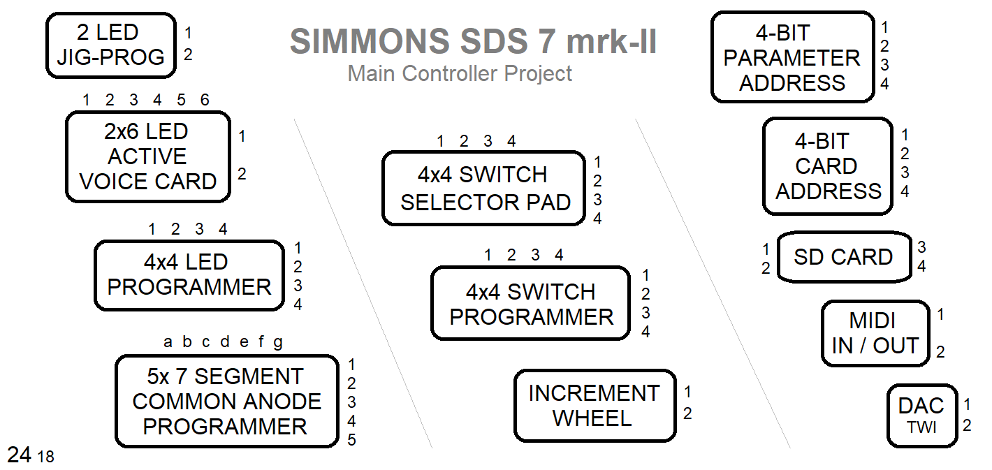
Display driver
Switch matrix
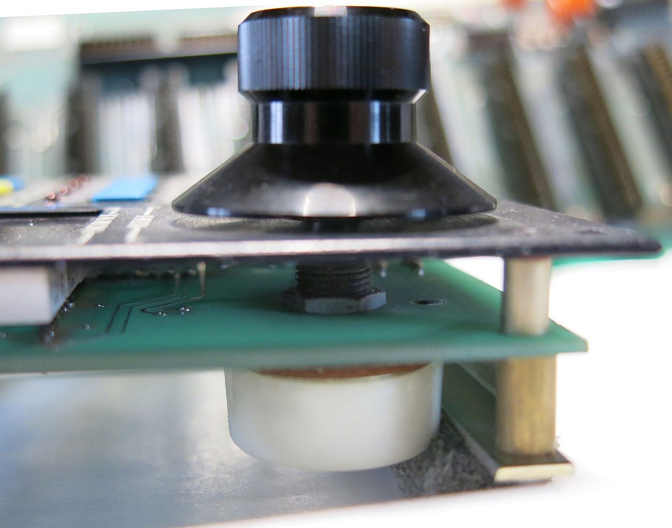
Increment knob
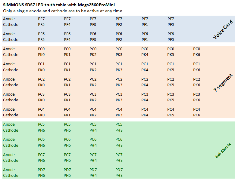
Refresh control voltages to 12 voice card slots with 15 (16) parameters each
Memory management
Selector Pad
MIDI Program Change
MIDI CC
MIDI trigger if enough free pins on the ATmel2560, else parallel MIDI device sharing opto coupler are possible with ATmel328 or similar
Software development are done with the Arduino IDE environment and libraries.
Another heavily used tool are Notepad++, a free source code editor.
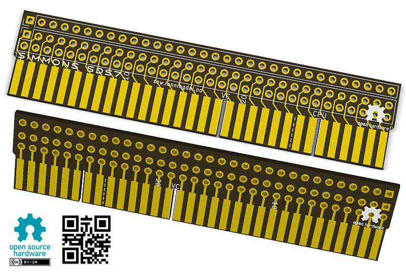
Ready for order at OSH Park
Please note the slot cutout for the key are made a little to narrow and need to be opened up using sandpaper or thin nail file. Or edit the KiCad file to create a wither slot before ordering.
Legacy memory cartridge planned to be replaced with SD Card memory.
Not owning a cartridge I'm lacking incentive for spending more time creating code for it than it takes for anyone to manually transfer settings to a spreadsheet. That sayed, it should be a straightforward project to create an adapter connecting to a computer for backup and converting to SD.
Original implementation of the first introduced Optical Increment Wheel make use of an additional comparator circuit on the CPU board. Although a faster µC will have better luck controlling the original optocoupler wheel it is not within the scope of this project to support it.
It should be easy to create a separate branch on GitHub for anyone wanting to code for an optical version. In current hardware there are four pins dedicated for the rotary encoder including 5V and ground. Two transistor might be enough to create needed hysteresis.
SDS7 update each voice card every 7.3ms (7.3kHz). There are two reasons for us to try increase this speed.
— First is to move the 'computer' noise from the backplane bus up in frequency to where it can be filtered.
— The other reason is to have the VC (voice card) updated so fast that a single VC can be played with new sounds loaded with different MIDI notes.
Probably the parts that will give first when speed is increased are the analog sample & hold circuits on the Hybrid modules for each VC. While it is expected to give functionality as today with some higher speed some cap values on the Hybrid might need 'tuning' for correct S&H time.
Part used here are HEF4067B, LM324 Quadruple op-amp and OTA's used are probably LM13700 (or LM13600).
Datasheet for DM74LS154 used to enable VC suggest worst case propagation delay around 35ns, 1000/35 = 28.5MHz. Luckily we are not able to, nor need we make speed in this region as the backplane probably will give us problems.
HEF4067B typical 60ns and have 385ns as worst case, 1000/385 = 2.6MHz
It seems all are good to go with regards to logical circuits involved.
Arduino MEGA2560 R3 compatible µC board
MCP4725 DAC DAC with I2C interface
MEGA2560 r3
eBay item 162593120234
Dupont wires
eBay item 201540635728
Plan is to use 2560 to both sink and source LED. To ensure 2560 aren't overloaded with misguided programming initial test on the port behavior show something interesting.
Pins sinking current is planned to be set to high impedance inputs to turn them off. As it turns out — if a pin has been used as output and set high the internal pull-up resistor are activated and will stay connected even when port data direction is altered to input. Code
        DDRA      PORTA     PINA
Input:  11111111  00000000  00000000
Output: 00000000  00111010  00111010
Input:  11111111  00111010  00111010
Input:  11111111  00000000  00000000

1th Port A is set to high-impedance inputs
2th Port direction is set to outputs and some pins altered
3th Port is back to inputs, but as seen no longer in
high-impedance. It seams port sets pullups and leave
them even when DDR (data direction register) change
4th same as 3th but PORTA=0 turns off all pullups
Trying to answer the question of how much current the new main controller need I found the datasheet for Mega2560 rather mutter. There are so many variables I ended up adding them all with this diagram and landed on approx 25mA for the m2560 + 50mA for the DAC. Total current the m2560 package can sink are 200mA.
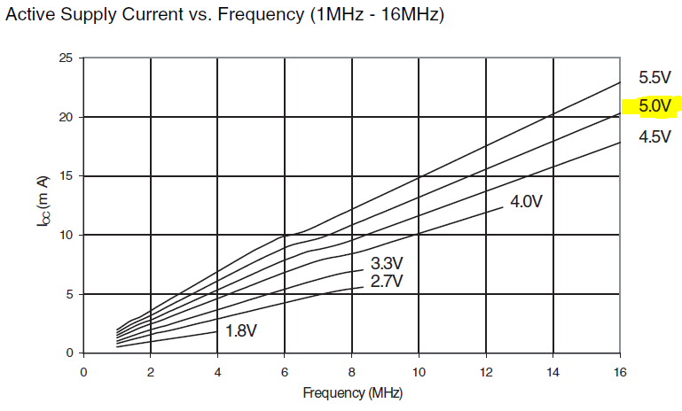
Probably the most current hungry load for the m2560 will be the 12psc HEF4067B. Total current for these are unknown as the backplane capacitor effect aren't know to us. But drive capacity for the m2560 pins are equal to the driver chip originally used in SDS7.
DAC input 2mA
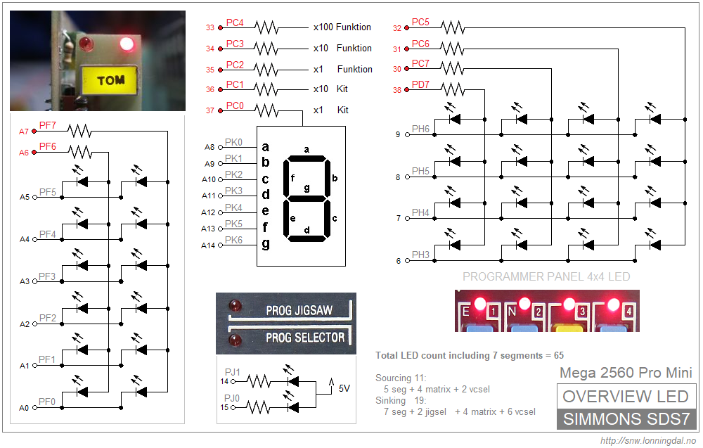
Programmer LED on VC will not be multiplexed to minimize noise on the backplane, 14mA when in edit mode.
Controller panel will only have a single 14mA LED on at any time.
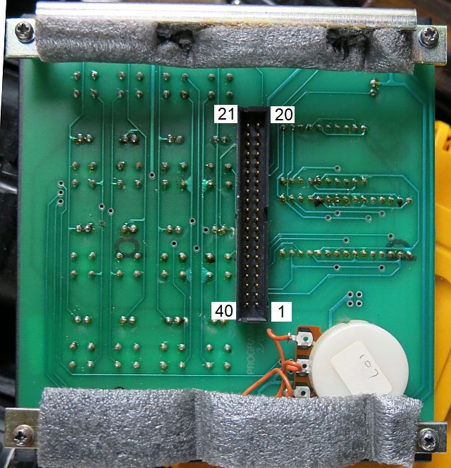
SDS7 backplane is really crowded. Finding a location to drill holes for MIDI connectors can be a challenge — at least if aesthetic is of importance.
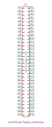
As memory cartridge will be replaced with SD card this slot might offer an option to solve our dilemma.
SDS7 cartridge slot seams to fit a DIN41612-B032F connector with 2,54mm (.100") pitch where only every second pin is mounted — meaning a more traditional 64 position female connector should fit.
Mouser offer two alternatives, Molex strait No: 538-85040-0127 and an angled version from Harting No: 617-09722646804.
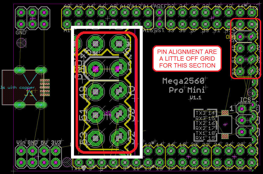 A slight deviation discovered for the Mega2560PM footprint. Stacking female headers close together might need this adjustment.
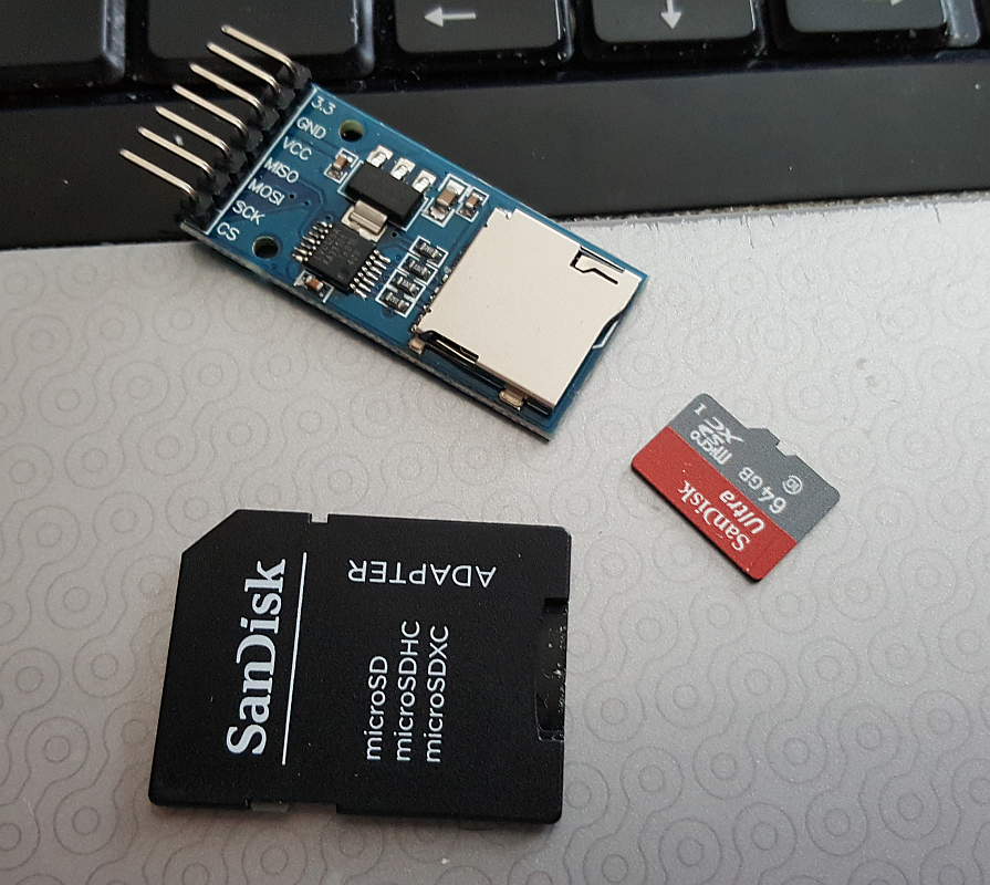 This SD card adapter has on-board 3.3V regulator and active 5/3.3V level shifting using LVC125A.
To write the character µ (micro) on a Windows computer hold down the 'Alt' key and type '230' or 'Alt+0181'.
sds7mc/proto4.jpg
To view high resolution images, right click on image and select View image or Save image
Select file from list below
Microchip ATmega2560 http://www.microchip.com/wwwproducts/en/atmega2560
Arduino Mega 2560 REV3 https://store.arduino.cc/arduino-mega-2560-rev3
Teensy library for KiCad https://github.com/XenGi/teensy_library
MIDI over USB https://github.com/tttapa/MIDI_controller/wiki/MIDI-over-USB
Calculate RC filter for PWM http://sim.okawa-denshi.jp/en/CRtool.php
Your comment are welcome