Skip introduction EPROM size Lets start simple More sounds Get me straight to EPROM splitter Smart Control SD Card Back to SDS 7 main page
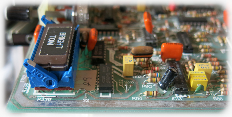
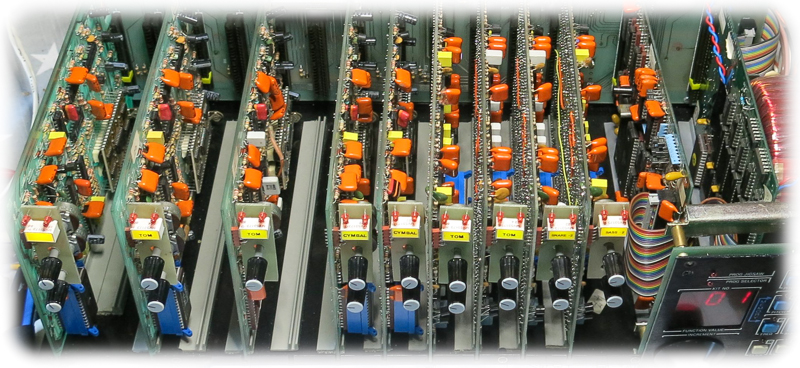
With the limitation of only one single sampled sound on each voice card I find it hard to decide on which sounds I want to implement before closing up my SDS 7. Even with ZIP socket installed on all cards it's still a rather fiddly job to replace any of the EPROM.
When I stated playing with ideas for a DIY version of the 20-85 board I first wanted to replace the EPROM with a memory chip and a MCU/SD card reader. But this turns out to be a more comprehensive project than I initially thought, especially if I wanted to build them in multiples. This project takes a simpler approach by first looking at a simple manual EPROM address selector, then add to this by investigating the possibilities to use a cheap MCU for easy sample selection from excising user panel or MIDI.
When preparing many of the 80’s drum machine samples found on the net for use in my SDS 7 I was surprised how useful many of the sounds at 4096 samples where. Even many of the very short sounds with 2048 sample length had enough information to create interesting percussive hits. What if I could combine several of those sounds on one or even several 27512 EPROM’s?
As it turs out this is quite easy to implement compared to the SD card project. The trick is simply to fool the voice card to believe it play a smaller EPROM, and then select different sounds by manually set the upper addresses A11-A15 (MSB) with switches.
Worth mention here is that we can create a multi sample EPROM containing up to four 8K sounds with a single 32K EPROM without any modification to the SDS 7 voice board. Any sound switching can be done on the EPROM.
We will need to do some soldering on the voice card if we want to utilize shorter samples than 8K, or use bigger EPROM 64K (27C512). Or if we want to use sounds with different size and still maximize sample count.
For ease of use we could replace switches with a 3£ Arduino MCU developer board and a single push button, pot or encoder to select sounds. With a MCU we can even add trickery like automatic sample switching.
20-85 board
Back in the 80’ Simmons Group Centre, US distributor of Simmons products had a PCB made that would hold four EPROM's. Often referred to as the 20-85 board. I’m told this board where a result of multiple requests from professional musicians wanting more versatility from they’re SDS 7.
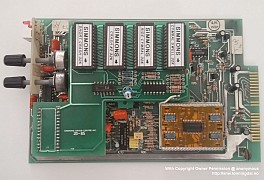
The additional PCB has logic to switch between the four EPROM from user frontpanel and save settings with drum-kits as usual. Early boards would use the Filter Resonance CV signal to select samples. Later boards utelize the Click Level. My understanding this add-on PCB board where only delivered ready assembled with the analog/digital voice cards. Story are that most of them went to endorsee musicians, very few were ever sold. Although what’s referred to as genuine old stock are still for sale on eBay early 2017.
The fact that we loose (can be combined) a CV line/control parameter for use as sample selection makes for some reservation among users, although the Click Level doesn’t seams as intrusive as the original Resonance as it can be compensated for in the samples used on the card.
Later Simmons UK relised the Dual Digital, where the analog oscillator where replaced with a copy of the already known DAC800 sample player.
E-prom size
By default the smallest EPROM SDS 7 voice card can be configured with are 8192 samples 8K EPROM (27C64). Max size are 32K (27C256), but can easily be modified for 64K (27C512).
- Configuration are a two part task
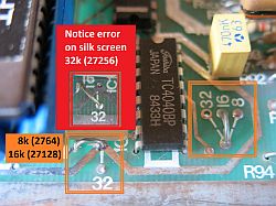
- - First set configuration for different EPROM sizes, for 8K and 16K EPROM pin 27 are set to
High(+5Volt) while 32K EPROM use this pin set to receive address A14 - - Then configure output from the binary address counter to send a stop signal to the sample clock generator when sample are finished played trough.
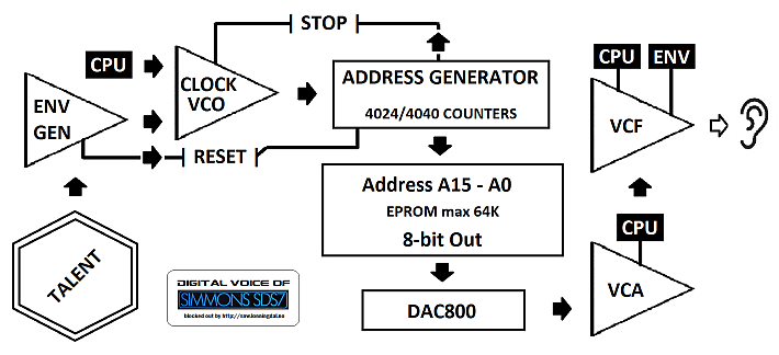
Or better, we could replace this stop signal from IC10 with MCU logic by hooking up IC10 Q5-Q10 to our MCU and use program logic to select which one to pass on to sample clock configurator on the voice card, enabling us to mix different sized samples on a single EPROM.
| bits | bytes | samples | seconds at 22050Hz | # of sounds with 512KB | CD4040 stop signal | EPROM pin(#) | last address | lenght |
|---|---|---|---|---|---|---|---|---|
| 512K | 64K | 65536 | 2.976 | 1 | Q10(14) | A15(1) | FFFFh | 10000h |
| 256K | 32K | 32768 | 1.488 | 2 | Q9(12) | A14(27) | 7FFFh | 8000h |
| 128K | 16K | 16384 | 0.744 | 4 | Q8(13) | A13(26) | 3FFFh | 4000h |
| 64K | 8K | 8192 | 0.372 | 8 | Q7(4) | A12(2) | 1FFFh | 2000h |
| 32K | 4K | 4096 | 0.186 | 16 | Q6(2) | A11(23) | 0FFFh | 1000h |
| 16K | 2K | 2048 | 0.093 | 32 | Q5(3) | A10(21) | 07FFh | 800h |
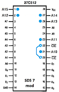
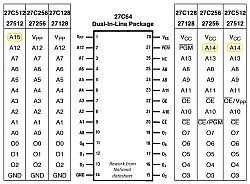
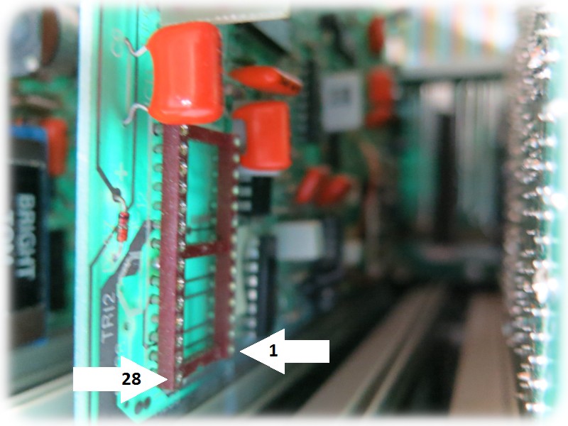
Shown here are the pins on the EPROM we need to focus on for any modification.
If setup include mutible EPROM's Output Enable and Chip Enable shold be held High at +5V for all inactive EPROMs. For the active chip OE and CE should be set Low - i.e. active-low as indicated by the bar above pin's function name.
This is probably not true for all EPROM’s, but from M27C256B datasheet we learn this device will reduce power consumption from typical 30mA to 100uA when CE are High
Lets start simple WARNING, NOT TESTED
Let us start with something simple, something nondestructive to our beloved SDS 7. Let’s try to make an EPROM containing 2 sounds.Quick refrence.
Step 1: Combine two compatible audio files from Windows console window
copy /b sound1.bin+sound2.bin MySound.bin
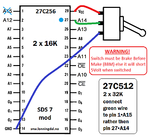
Step 2: Solder switch to EPROM as shown in figure to the left.
WARNING!
Switch must be Brake Before Make (BBM) else it will short 5Volt to ground when switched. If you’re not sure what switch you have go with the more advanced version implementing a resistor. This version are more to show principled function anyway.Here we will use an 27C256 EPROM, often referred to as a 32K EPROM. Table 1 show us that this EPROM can hold up to max 32768 samples. For this exercise to work we need two equally long samples, trailing or leading silence in the sound are valid of course. But the two samples must each be exactly 16384 samples long (32768 / 2). The main SDS7 page has some tips how to preparing sounds. If you're not ready to start combining files at this time please feel free to use this example file.
What let us stuff multiple sounds in a single EPROM are caled addresses. In text and program code an address are defined in Hexadecimal, but on the physical EPROM device the pins functionality are Binary, counting from A0(LSB) - A15(MSB). To visulize what pins are active for any given address defined in Hexadesimal use Windows Calculator in programmer mode or an online Hexadecimal to Binary Converter.

From a musician perspective the actual sample make more sense as we edit in samples length, hence decimal value are also useful to reference.
In more advanced devices like game cartridges, firmware and alike one can access any address location inside the EPROM at any time. But the simple sample playback engine in SDS7 are designed to just flush out complete content counting up from address 0h to max address as defined by EPROM size configuration.
Please look at column last address in Table 1. Principle are we take last address for the EPROM we deside to use and divide by number of sounds we want. The result + 1 we can think of as start position for the next sound we add. Or to simplify, in the table find the EPROM size equaling our sample size and use that address +1. For our example with the 32K EPROM sound #2 start at 3FFFh + 1 = 4000h as found in the table row for the 16K EPROM.
Luckily non of this math is actually important for us to understand unless we try to combine sounds in programmer software. Table 1 and Table 2 have all the information needed and rule are simple, every step up in EPROM size is always doubled. And number of combined sounds must always be an even number. More on that later.
Now take a look at table column EPROM pin(#) for the EPROM size we use in this example, the 32K. It list A14(27) (address selector pin A14 as physical pin number 27 on the chip). With the possibility to access this pin the complete content from address 0 to 7FFFh is available. If the SDS7 voice board are correctly configured for 32K EPROM the sample engine will set every possible address with the speed set with the Digital Pitch (VCO oscillator speed and sample playback rate are 1:1).
For our 32K EPROM containing two sounds result might not be that existing right now, so let us finally look at the secret sauce that let us split it into two seperate sounds.
First trick are to configure EPROM setting on the SDS7 voice card.
The important setting are the wire jumper furthest away from the EPROM. This jumper ensures that the sample player stop after one complete sample has played, for our example use position 16K meaning the stop signal are sent after 16384 samples at address 4000h. Remember jumper setting closest to the EPROM socket are there to set pin 27 at +5V for 16K and smaller EPROM. Guess what, this is the pin we are going to do trickery to. Leave this jumper open for now.
What do we expect to happen now? Yes it will play one sound, from address 0 to 3FFFh (if we are lucky). Look at the table again, but this time find EPROM size 16K. SDS7 will access last address 3FFFh with A13 pin 26, meaning it will never be able to access addresses from 4000h as it is told to sendt clock stop signal to the digital oscillator when it reach 4000h. Remember we set the EPROM size configuration on the voice board at 16K.
To access contend from 4000h to 7FFFh we need to activate pin A14(27) while still have SDS7 configred to stop after 16384 samples.
If we connect jumper setting closest to the EPROM socket to the 8-16K position it will now play from address 4000h as this jumper connection select between +5V (8-16K) or connect A14(27) to the address counter in the 32K position.
Practical implementation it would be tempting simply to have a switch to close or break this jumper. But we are not supposed to keep address pins floating as its not certain it’s state will stay Low. That's why we switch pin 27 either to ground or +5V.
Next paragraph we look at how to implement what’s called pull-up resistor for the binary address pins, with less risk of shorting your 5Volt supply.
The sample engine address counter stop signal are configured on the voice board to fit only one size EPROM. Therefore multi sample EPROM must be divided into equally sized samples. And to simplify manual addressing we prefer to use even number of samples, i.e. 2, 4, 8. Of course short samples with added silence to fill the needed address space for combination with longer samples are possible.

More sounds WARNING, NOT TESTED
| # | EPROM | address | A15-A11 | 2048 | 4096 | 8192 | 16384 | 32768 | 65536 |
|---|---|---|---|---|---|---|---|---|---|
| 01 | 27C16 * | 07FFh | 0000 0 | X | |||||
| 02 | 27C32 (A11) * | 0FFFh | 0000 1 | X | X | ||||
| 03 | 17FFh | 0001 0 | X | ||||||
| 04 | 27C64 (A12) | 1FFFh | 0001 1 | X | X | X | |||
| 05 | 27FFh | 0010 0 | X | ||||||
| 06 | 2FFFh | 0010 1 | X | X | |||||
| 07 | 37FFh | 0011 0 | X | ||||||
| 08 | 27C128 (A13) | 3FFFh | 0011 1 | X | X | X | X | ||
| 09 | 47FFh | 0100 0 | X | ||||||
| 10 | 4FFFh | 0100 1 | X | X | |||||
| 11 | 57FFh | 0101 0 | X | ||||||
| 12 | 5FFFh | 0101 1 | X | X | X | ||||
| 13 | 67FFh | 0110 0 | X | ||||||
| 14 | 6FFFh | 0110 1 | X | X | |||||
| 15 | 77FFh | 0111 0 | X | ||||||
| 16 | 27C256 (A14) | 7FFFh | 0111 1 | X | X | X | X | X | |
| 17 | 87FFh | 1000 0 | X | ||||||
| 18 | 8FFFh | 1000 1 | X | X | |||||
| 19 | 97FFh | 1001 0 | X | ||||||
| 20 | 9FFFh | 1001 1 | X | X | X | ||||
| 21 | A7FFh | 1010 0 | X | ||||||
| 22 | AFFFh | 1010 1 | X | X | |||||
| 23 | B7FFh | 1011 0 | X | ||||||
| 24 | BFFFh | 1011 1 | X | X | X | X | |||
| 25 | C7FFh | 1100 0 | X | ||||||
| 26 | CFFFh | 1100 1 | X | X | |||||
| 27 | D7FFh | 1101 0 | X | ||||||
| 28 | DFFFh | 1101 1 | X | X | X | ||||
| 29 | E7FFh | 1110 0 | X | ||||||
| 30 | EFFFh | 1110 1 | X | X | |||||
| 31 | F7FFh | 1111 0 | X | ||||||
| 32 | 27C512 (A15) * | FFFFh | 1111 1 | X | X | X | X | X | X |
| 32 | 16 | 8 | 4 | 2 | 1 |
High state i.e. 1.
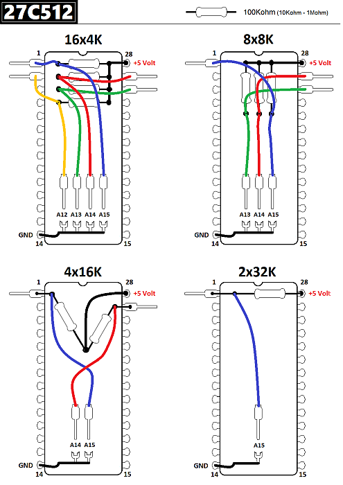
In high speed devices value of resistor can be critical, but for manually switching like we do here one can use near any value from 10K-1M ohm. As general rule higher value give lower current draw, slower switching speed, and to high value fails to alter pin state. In doubt, something not working as planed or you need to order new resistor anyway go with values between 10K-100K.
Worth noticing if switching is planned with a MCU these resistor usually are built into modern SOC (System on a Chip) like the ATmel328 used on Arduino boards.
When we switch the junction between the resistor and the EPROM pin to ground the state switch to Low 0. Please be careful to ground the correct side of the resistor. It is the EPROM pin that shall to ground..
Illustration try to show which pins need to bent out of the EPROM socket. Except +5V and GND none of the pins that are soldered to shall be seated in the EPROM socket.
How to use Table 2
First decide on EPROM size: 64K (27C512)
Then sample length: 8192
In Table 2 find column that match selected sample size 8192, search from top to find the first row that has an X.
Follow this row to column EPROM and make note of max binary address pin (following EPROM type), here (A12). This is the highest pin (MSB) that the address generator will address automatically.
Upper address pin is (A15) as noted with the selected EPROM type 27C512. Now we know how many address pins need to be altered by the modification (15-12=3).
Take note of binary addresses for every X marked row in the 8192 column from selected EPROM type following the column upwards. For our 64K (27C512) we find that a total of 8 sounds at 8192 samples each will fit, and that we must manually address the following binary pins.
- A15-A13
- 01: 000
- 02: 001
- 03: 010
- 04: 011
- 05: 100
- 06: 101
- 07: 110
- 08: 111
Let’s try another to confirm: 32K (27C256) with 8192 sample length give 4 samples at A13 to A14.
- A14-A13
- 01: 00
- 02: 01
- 03: 10
- 04: 11
| Decimal | Hexadecimal | Binary |
|---|---|---|
| 0 | 0 | 0000 |
| 1 | 1 | 0001 |
| 2 | 2 | 0010 |
| 3 | 3 | 0011 |
| 4 | 4 | 0100 |
| 5 | 5 | 0101 |
| 6 | 6 | 0110 |
| 7 | 7 | 0111 |
| 8 | 8 | 1000 |
| 9 | 9 | 1001 |
| 10 | A | 1010 |
| 11 | B | 1011 |
| 12 | C | 1100 |
| 13 | D | 1101 |
| 14 | E | 1110 |
| 15 | F | 1111 |
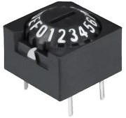
Manual switching of up to 4 address pins can be realized with a HEX/BCD 0-F Scale, 16-positions rotary switch.
These switches ususlly have 5 pins, one common pin to ground, and four pins to EPROM pull-up junctions.
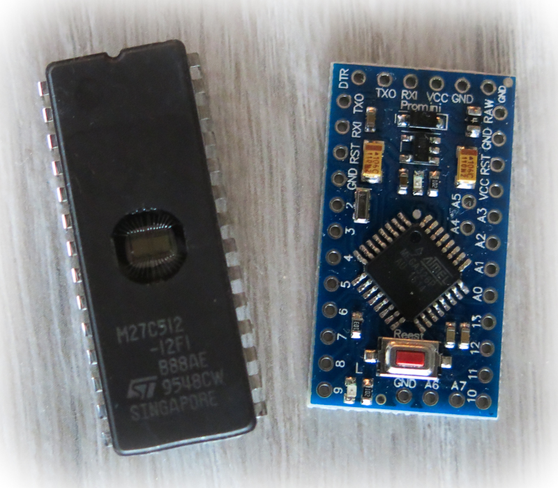
Smart control
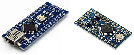
5Volt ATmega328 16MHz developer boards. Arduino Nano to the left and Pro Mini to the right. They have indicial function except when being programmed. While Nano has USB to serial interface to interconnect with the programmer software, 5V power and automated programmer reset, the Pro Mini will need external power, USB to serial interface and manual programmer activation/reset. Nano are by far my favorite to develop on, but the Pro Mini will a better partner in SDS7 when code are finished.
If using a MCU to select sounds, and if we have a free voice card slots we could tap into the CV signals sent from the main CPU board for the free slot. For instance we could hook up the MCU to decode the four address pins [5, 7, 9, 11], enable pin [4] and hook up MCU’s AD converter to CV line [12] to read the 0-2.5V control voltage. This CV line have 8-bit resolution and should without too careful calibration be able to function as sample selector as it does on the 20-85 card.
This scenario are interesting for two rather important reason. Sample selection will be stored as part of the drum kit and we have access to alter sounds without removing the cover or drilling holes for selector switches on our vintage synth.
We could even centralize this by hooking up one MCU to a single voice card bus connector, then send sample select parameter to a dedicated MCU on each voice card through a two wire I2C signal path.
Another idea could be to implement dynamic multi sample switching by hooking up the MCU’s AD converter to the envelope generator. Or do simple sample trigger switching where every hit or “divided by #” will move to a new sample either by random or to next address.
Example below tap into the Click Level CV as the 20-85 card and use ATmega328 internal 10-bit DAC to read the decoded voltage on pin 21 on the Hybrid module. The Arduino board can be soldered on top of the EPROM direcly or with a pin header.
A popular way to easily add multiple EPROM without dedicated PCB are to stack them on top of each other. If DIL sockets are used rather than soldering chips together one can reprogram EPROM if needed.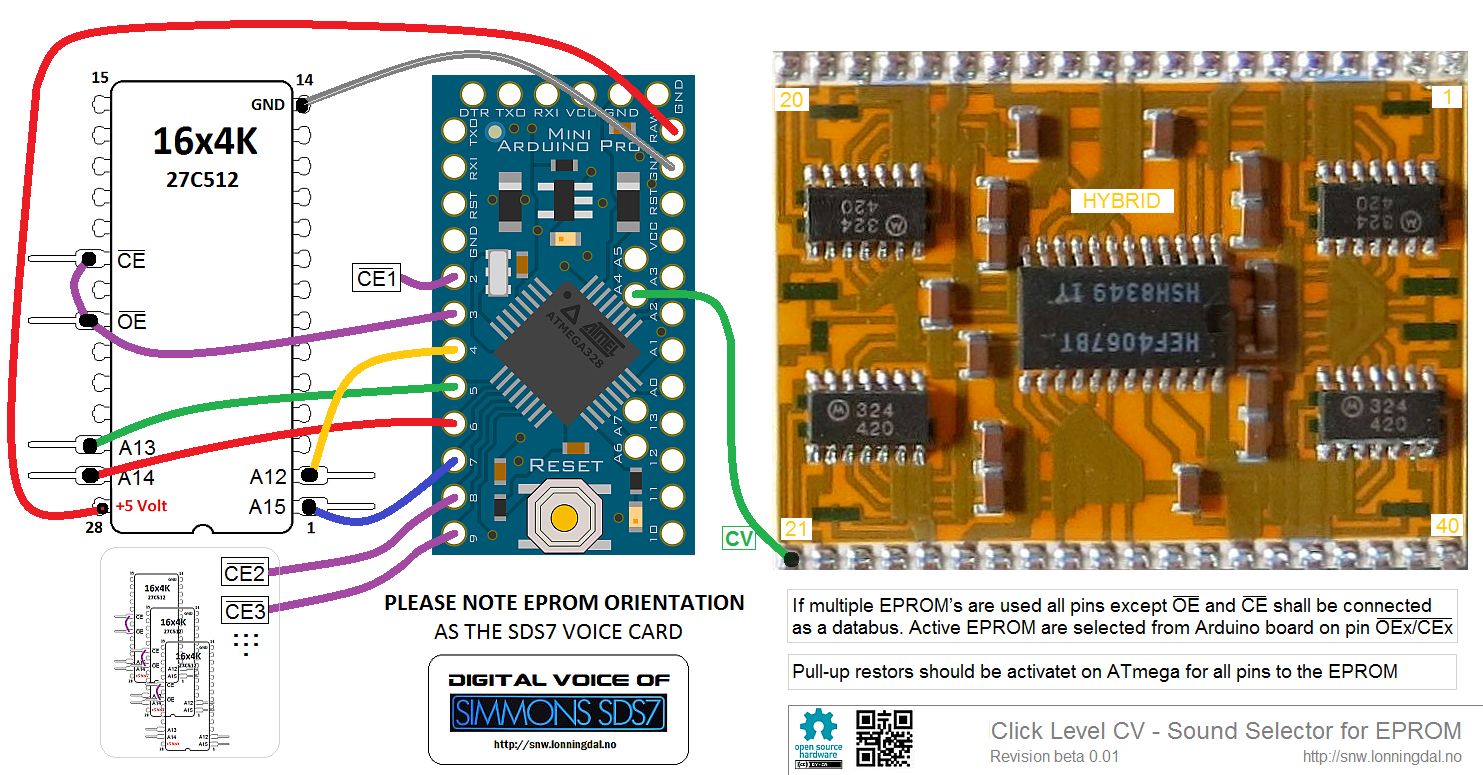
SD memory card
In all my research up until now my thinking regarding use of memory card where related to an EPROM emulator. But interfacing 2-byte parallel addressing to serial memory there are a few issues. Although not very complicated eventually in the end it would need a PCB design for surface mounted chips, or hunt for parts no longer in production.
But what if we skip the 2-byte address counter? Rather than have the two counter chips on the voice card address the old EPROM we replace the EPROM with serial EEPROM or a SD card reader that are clocked from the original analog clock on the voice card directly. Thereby removing the need for 2-byte address interface. In principle function as a simple 8-bit serial to parallel interface.
Okay okay, I know - it’s an vintage sample play back engine, don’t fiddle with it. But how much character can two CMOS counters outputting a 2-byte address have on tone? If any, careful coding could simulate a few simple artefacts. The “digital” clock will still be analog and my believe are that if this end of the sample engine have character, its coming from the clock. Well actually, I already measured this VCO clock to be very imperfect so glad we’re keeping it.
The idea is an Arduino Nano/Pro Mini board (low cost and ease of use with 5V) with an SD card holder to replace the EPROM. Total cost without memory card around 4£.
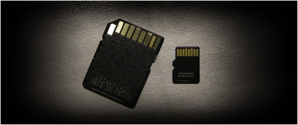 Any discussion herein refereeing to SD Card do include both standard SD Card and micro SD Card as they interface identical. Practical implementation micro SD Card seems like a better choice for internal use in the SDS7.
Interface
- Output from Arduino
- - 8-bit digital audio, parallel data as from EPROM [EPROM socket pin 11,12,13,15,16,17,18,19]
- - Stop signal (at end of file) [to vc EPROM configuration common pin]
- Input to Arduino
- - Clock (speed from “Digital Oscillator”) [from vc IC9 CMOS4024 pin1]
- - Reset pulse form the trigger input [from vc IC9 CMOS4024 pin2]
- - +5V [from vc EPROM socket]
- - GND [from vc EPROM socket]
Notes on clock, sample rate and data transfer speed

Measured clock speed out of the VCO driving the address counter in my SDS7 proved not to reach 44.1kHz. But it seems the intention where to do sample rates from approx. 800Hz to normal CD-DA.
As we are working with 8-bit samples conversion to data transfer speed is simple. Our serial to parallel conversion must be capable of transfer speed up to 44.1kB/s (6.4kbps – 352.8kbps). The good folks behind vital Arduino library’s has stated that transfer speed for SD card are expected to be around 600kB/s with ATmega328, giving us plenty of theoretical overhead.
Things to investigate:
- Do SD card read speed have any issue on the Arduino platform, like how does the SD card read buffer work. Is it possible to stream directly from memory card or are manual buffering necessary?
https://www.arduino.cc/en/Reference/SD
- Ideally we should only need one memory card for all voices. Wonder if we could add SRAM (23LC1024) to each voice card with a dedicated MCU, and then have one central MCU with card reader for sample selection and distribution to voice cards when new kit are selected and at power up. As we with a solution like this would load files and transfer samples to be streamed from memory more advanced sample handling can be implemented, like conversion from 16/44.1 to 8-bit unsigned. Although multible SD cards are both cheaper, faster to switch between kits, and much simpler to implement.
http://www.microchip.com/wwwproducts/en/23LC1024
- How to select and control sample collection from user-panel or added controls?
- What direction do sample data have? LSB to MSB or MSB to LSB?
-
-
There are some exciting possibilities if this is doable. I can think of several already.
- 8-bit WAV might be possible without need for Unsigned conversion
- Basic sample editing from back then like start-loop-reverse-end could be possible.
- Arduino SD class support FAT32 and folder structure which give room for lots of files on a single card,
- No need for fixed sized files, Gate input rather than trigger might open up for long samples.
- With more advanced coding and interconnection could evolve to auto tuning.
- Tapping into envelope or any control parameter could be used for dynamic multi sample triggers, sequence of triggers and so forth.
- Could interface with computer over USB for file transfer, but that one is not high up on my list.
- Play waveforms direcly from code/memory as a DCO rather than samples
- Create triggers. i.e. after a defined delay or numbers of samples played do auto-loop, switch to new sound or send trigger to other voice cards.
-
Hook-up diagram for proof of concept, test if we can play one single sound.
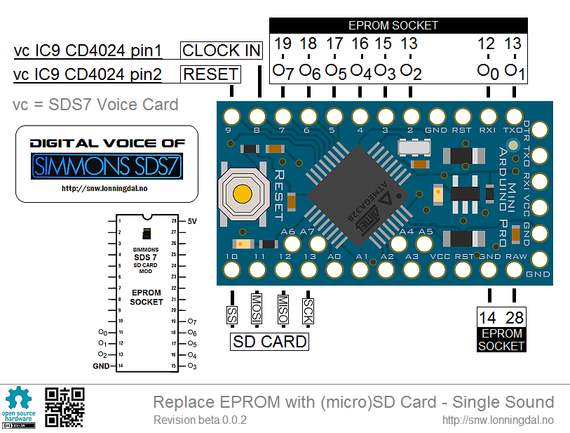
arduino sketch comming here...
Selecting sounds – early ideas
Global – All voice card select equal numbered sounds. User need to synchronize contend on all SD cards to make useful samples sets for a kit. Do not need to but can be be controlled from SDS7 bus board.
Plus One – Voice card slotted in position 1 will listen to parameter changes for slot 2. i.e. the next slot must be free or both sample selection and sound adjustment will happen. Can be implemented as add-on bus connector or simply soldered to address pins on the voice card.
Steal One – Selection are done similar to 20-85 add-on PCB, i.e. listening in on Click Level or disable this CV. If the volume knob on the voice card are seldom used one could reroute this potentiometer to adjust Click Level manually.
Analog Pot - As stereo bus are rather noisy and volume are near always set to max, use Volume potentiometer for sample selection. Either cut two PCB traces or lift output leg on resistor R232, R233 and input leg on R22, R23 and solder all four legs togehter.
Next diagram suggest a way to hook up for sound selection that can be stored with drum kits as described under One For All.
We need to tell the MCU which of the 16 control parameters we want it to respond to. Easy to hard code in our sketch, but then we cannot easily move voice card to another position and maintain logic use of sample selection from user panel. Voltage on analog input A5 is read at power up and MCU stores a 4-bit value for reference (use Reset button for quicker calibration rather than the power switch). Suggested value for a trimmer 5K-10Kohm
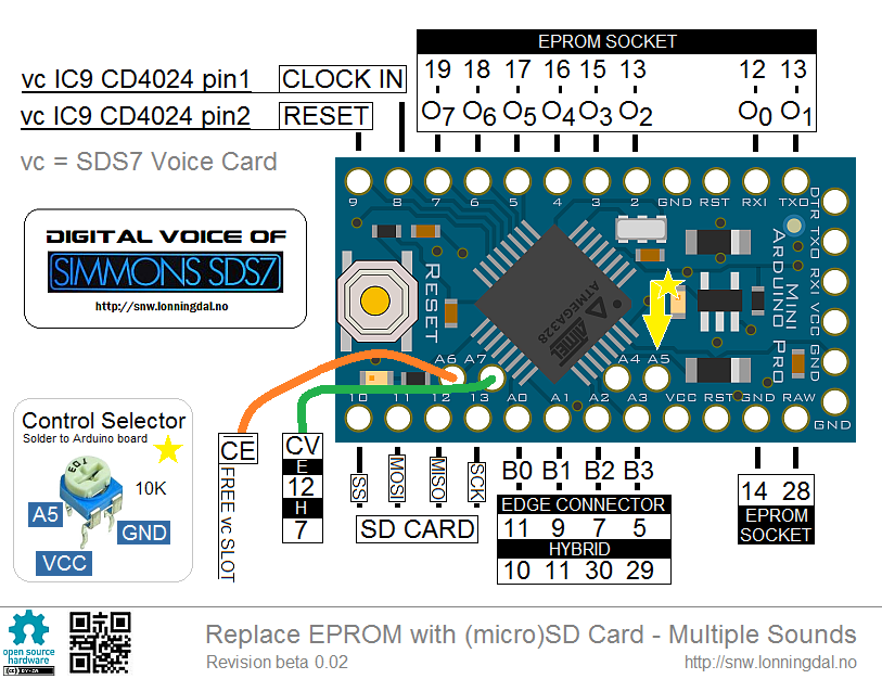
arduino sketch comming here...
One For All – Each voice card listen on address bus for sound selection. One single free* slot are selected to be used as master.
EPROM/vc are then addressed counting from top left moving to the right. i.e. vc 1 sample selection are controlled from Analog Pitch. vc 2 from Analog Bend. vc 3 Analog Modulation and so on.
Bottom row of buttons might be used with creative press & "press another before timeout" for sub menus to access folder selection - theoretical 256 sounds x 256 folders x number of vc you have installed.
Probably most practically implementation are to hook up to address and CV pins on each vc, and then either interconnect a new wire to select sample modules, or use a free trace on the bus PCB board (backplane).
(*) Do not need to be free, but expect interesting sounds to come from this card position.
SD Card Voltage
For easy interconnection with SDS7’s 5Volt logic Arduino board used are 5Volt tolerant. But all SD Cards are 3.3Volt with typical tolerance 2.7V to 3.6V.
When buying SD card reader for Arduino make sure you get one with active 5/3.3V level shifting like LVC125A or similar, not just passive resistors as the signal rise time can be to slow for 8 MHz SPI bus speed. On board 3.3V regulator to power the card are also helpful.
Card must be formated as FAT16 or FAT32 with SD Card Formatter. SDXC (64GB+) are supportet if reformated as FAT32
Arduino current draw
| ATmega328P Pro Mini Version | PWR Source | State | 5.0 V @ 16 MHz | 3.3 V @ 8 MHz |
|---|---|---|---|---|
| Unmodified | RAW Pin | ACT | 19.9 mA | 4.74 mA |
| Unmodified | RAW Pin | PDS | 3.14 mA | 0.90 mA |
| No Power LED | RAW Pin | ACT | 16.9 mA | 3.90 mA |
| No Power LED | RAW Pin | PDS | 0.0232 mA* | 0.0541 mA* |
| No Power LED, no Regulator | VCC Pin | ACT | 12.7 mA | 3.58 mA |
| No Power LED, no Regulator | VCC Pin | PDS | 0.0058 mA | 0.0045 mA |
| ACT - Active Mode PDS - Dower-Down Sleep with Watchdog Timer enabled |
||||
Interrupt for Clock & Reset inputs
Plan where to use interrupt for both clock and reset inputs, and use one of the two 8-bit ports (PB, PD) on the ATmega328 for fast bit shifting of 8-bit parallel audio data. Being able to set only one port on the SoC I believe is very beneficial for speed optimizing a project like this rather than hook up “any” free pin and code high/low state.
As it turns out when planning actual pin configuration we learn the SPI interface for SD card take four pins (10, 11, 12, 13) on Port B. The planned interrupt are only available on pin2 and pin3 which belong to Port D. Meaning there are no free 8-bit ports if external interrupts takes priority in this project.
An alternative small developer board utilizing a different SoC, the Pro Micro have the same problem. Although ATmega32U4 used on this board has loads more external interrupt pins (0, 1, 2, 3, 7) their all part of Port D. And the SPI interface are on the same Port B as ATmega328.
It seems interrupt are not happening with any of these really cheap and small developer boards. Although probably not a real problem unless we need to do loads of data cash maintains, and maybe timing issues when browsing for new samples.
Where to hook up to tap existing CV value
On the 40 pin Hybrid module the chip in the middle CD4067 are responsible for switching the CV line to the corresponding analog VCA circuit.
- Click Level pin 21
- Filter Resonance pin 36
Where to hook up to read card settings from CPU/Memory
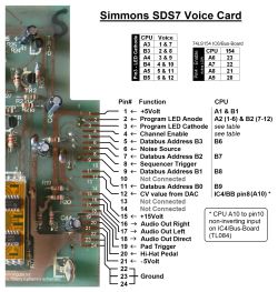
4-bit address for currently updated parameter are available at voice card edge connector pins 5[B3], 7[B2], 9[B1], 11[B0] and CV value on pin 12 are all connected to the common bus board. All of these pins are also represented at the Hybrid module (10, 11, 30, 29, 7, CE 31), if you're inclined to solder on here.
Pin 4 function as CS (Card Select) are set active Low when new CV voltage are ready for the currently updated voice card. To clarify, this pin 4 is unique for each of the 12 voice card slots. Although positioned on the same location it is not buss connected like address and CV.
Remember we are interested in a free voice card slot so tapping into this signal can be done with a custom edge connector, soldering to the bus board or directly to one of the pins on IC6/Bus-Board (74LS154). If more than one CS are needed one could tap into the address input on IC6.
Note on Teensy boards
I’m sometimes asked if I've heard about the Teensy boards from PJRC. Sure I have, the popular Sequential P5 CPU upgrade use a Teensy. Thats’s how I first learned about the possibilities with small SoC on a ready to go developer board.
Personally never had my hands on any of them but I’m sure they’re great powerful boards. The Teensy 3.5 seems near perfect for this project with 5Volt tolerance and on board SD card reader. It might even have the pin count and speed to function as EPROM simulator.
Sadly shipping alone to Europe for a single Teensy board can get me 10 pcs “Pro Mini Atmega328 5V 16M” of eBay, shipping included. Although not fair comparison the Open Hardware licensed ATmega boards floating eBay are dirt cheap and impossible to compete with. If its lower specification meet the requirement why pay more?
Comments
Your comment are welcome
