This H10 where received as partial functioning. General cleaning of all switches with Arrow Lotoxane and oiling of the axel for AM tuner where done. Axel where really stuck and afer some jiggeling what made it come loose where to remove the E-ring on the axel and then press the axel down into the houseing of the variable capacitor while turning back and forth. Take care not to damage the tiny fragile brass and aluminium gears. Had to shorten the AM dial cord 2-3mm to get better grip.
Mains wire for the transformer where moved from the 220V tab to the 240V position (outer tabs) and 25V PSU adjusted accordingly (VR R1002). Actually after the primary winding change voltage dropped to 25.1V.
Quiescent current where now low around 5-6mV after 15 minutes. Adjusted to 11mV according to service manual. There are some that recommend turning it a few mV higher for better sound quality. But have to familiarize myself with stock setting before setting out on that journey.
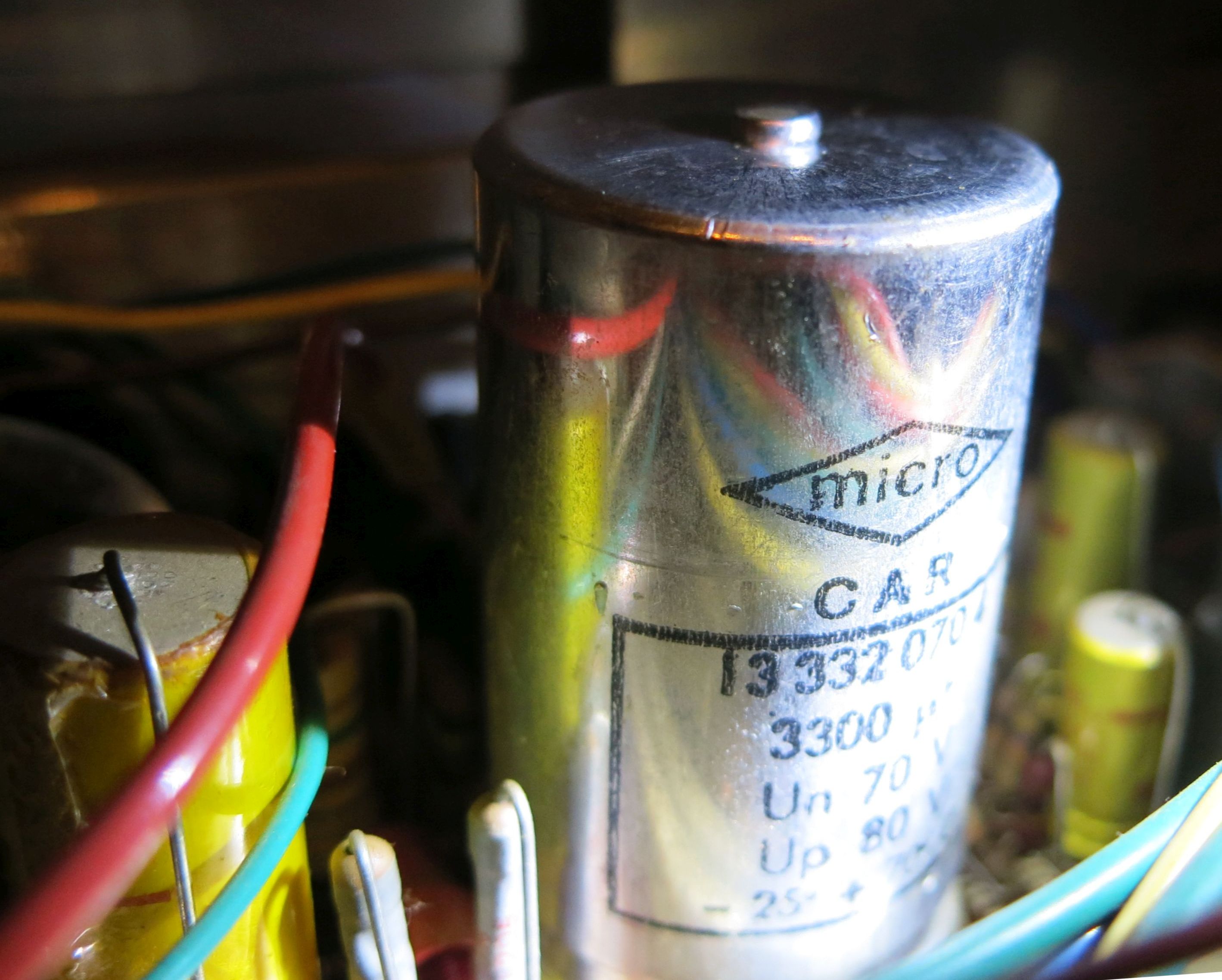
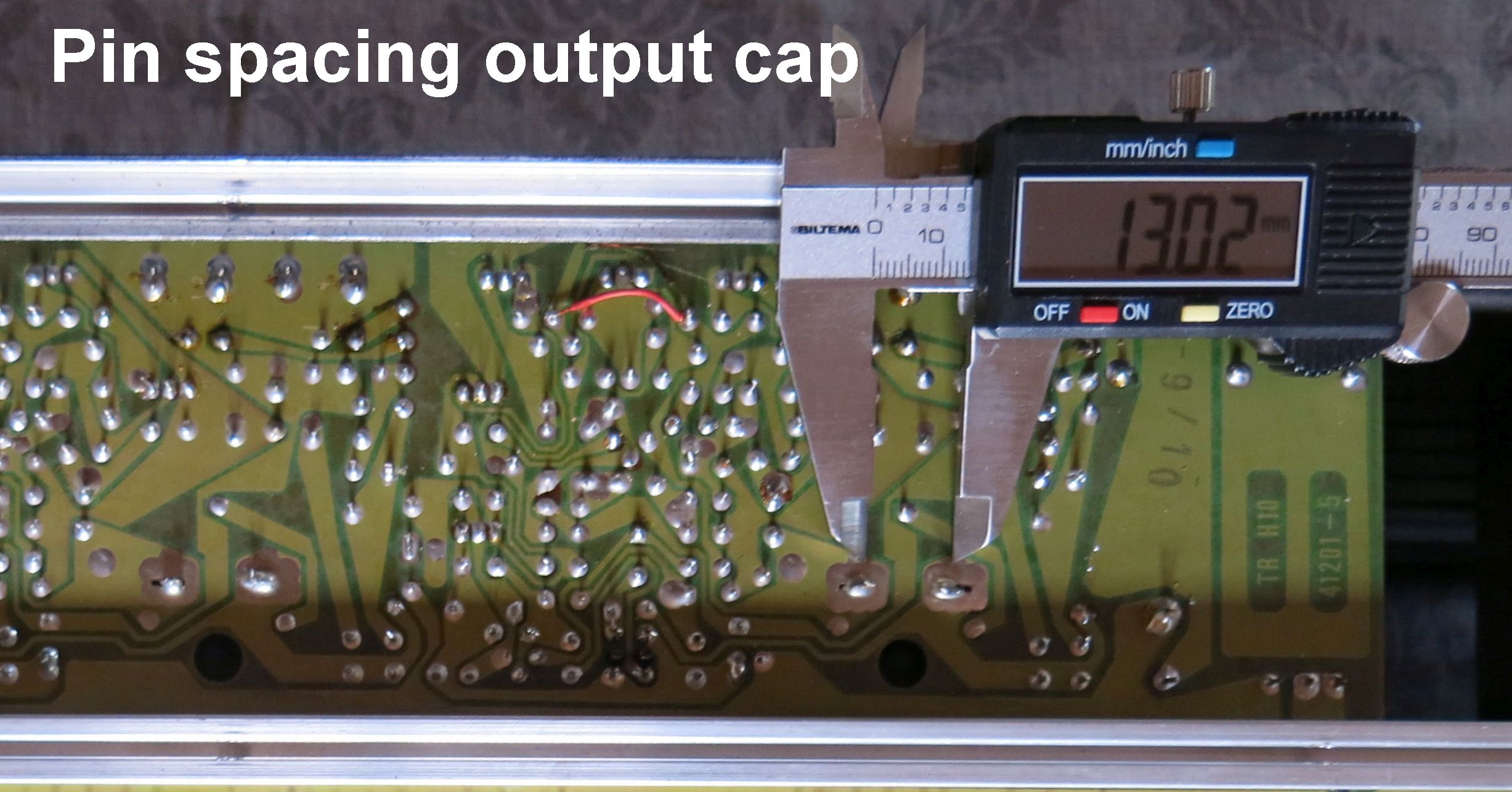
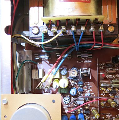
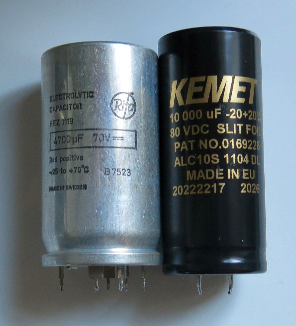
Original 4700µF capacitor where replaced with 10.000µF based on multiple recommendations. A new hole had to be drilled for the large cap. Actually, the 10.000µF cap are smaller than the original, but have a different foot print. 1.5µF/100V film cap where soldered on underside of PCB over the big cap terminals using free holes left from the original cap.
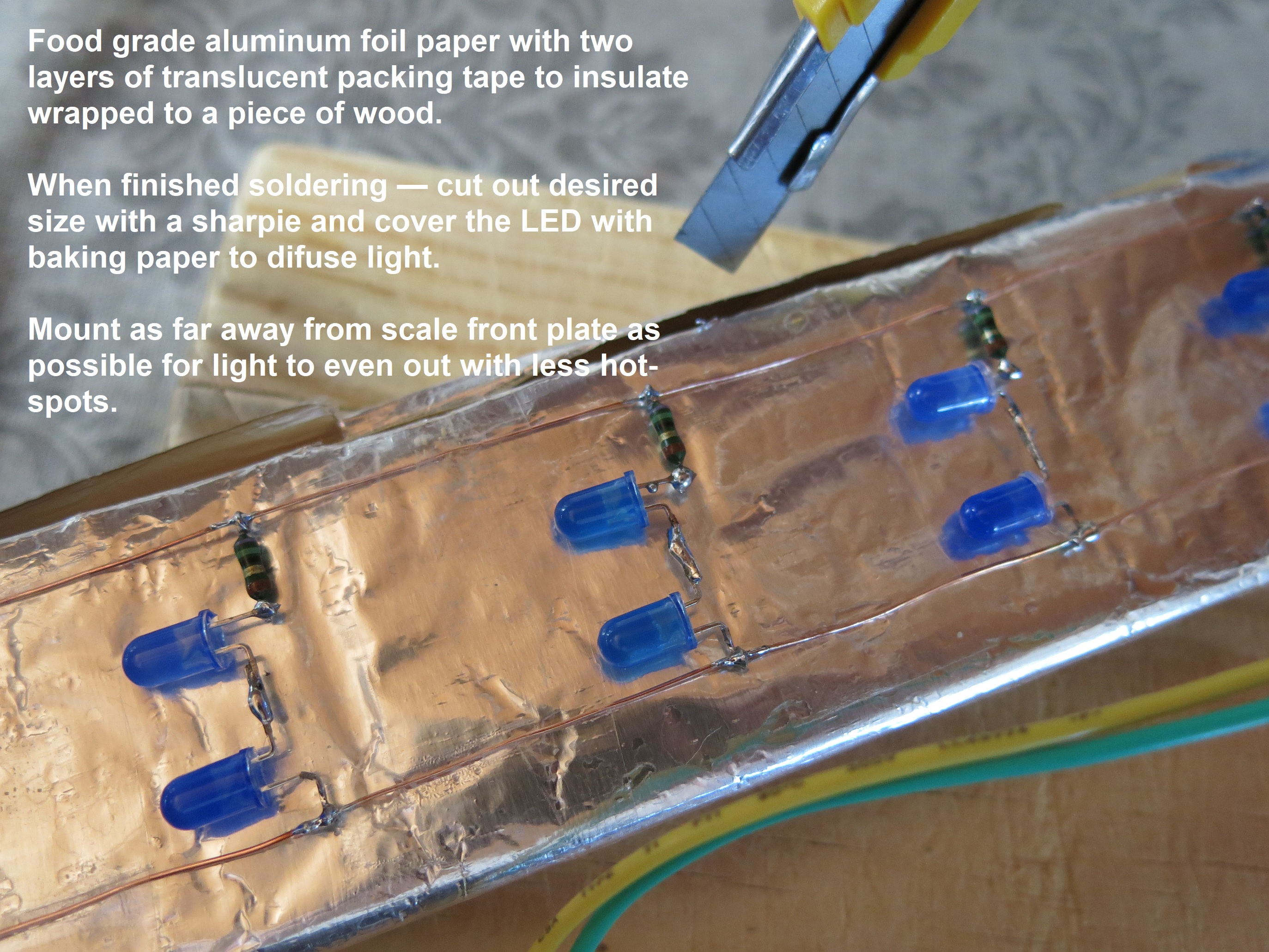
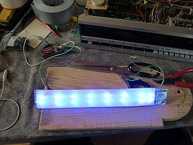
Only a single bulb out of eight 6.3V/320mA E10 bulbs for the radio scale panel where lighting. Rather than replacing all of them with new bulbs the idea to use LED open up the possibility to have this powerful 5.8V secondary transformer winding powering a Raspberry Pi (RPi) mini computer to give Internett radio in place of the now closed Norwegian FM radio network.
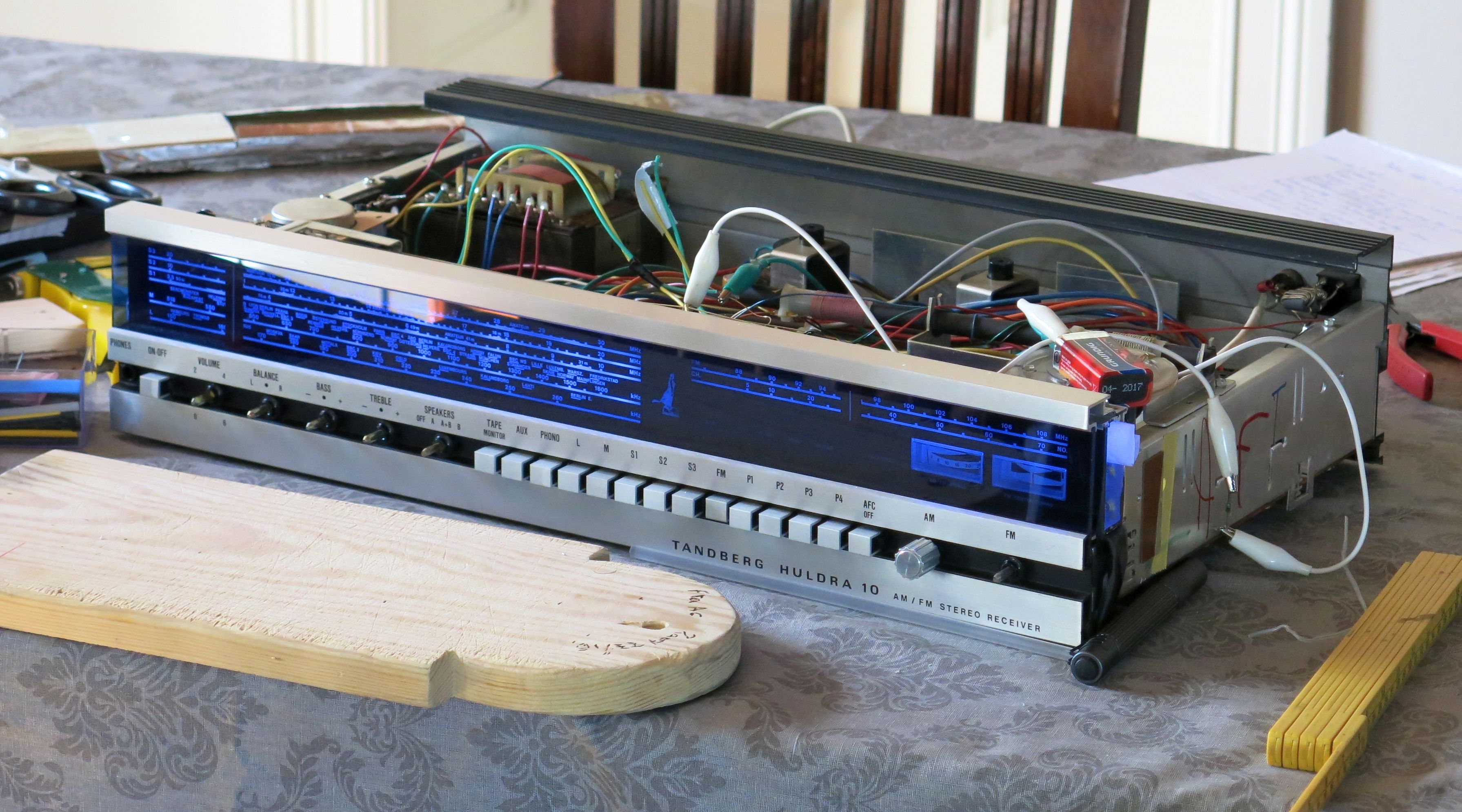
White LED where first tested with decent result. Front glass on these old Tandberg receivers are tinted blue. While they normally fade when exposed to UV light this specimen still have a clear deep blue color which really pop when scale where backlit with blue LEDs. For AM scale there are now total of 16 LED and 6 for the FM scale. Huldra, the old dame emblem will have her own LED up her back — planned to be lid up when there are an Internett connection.
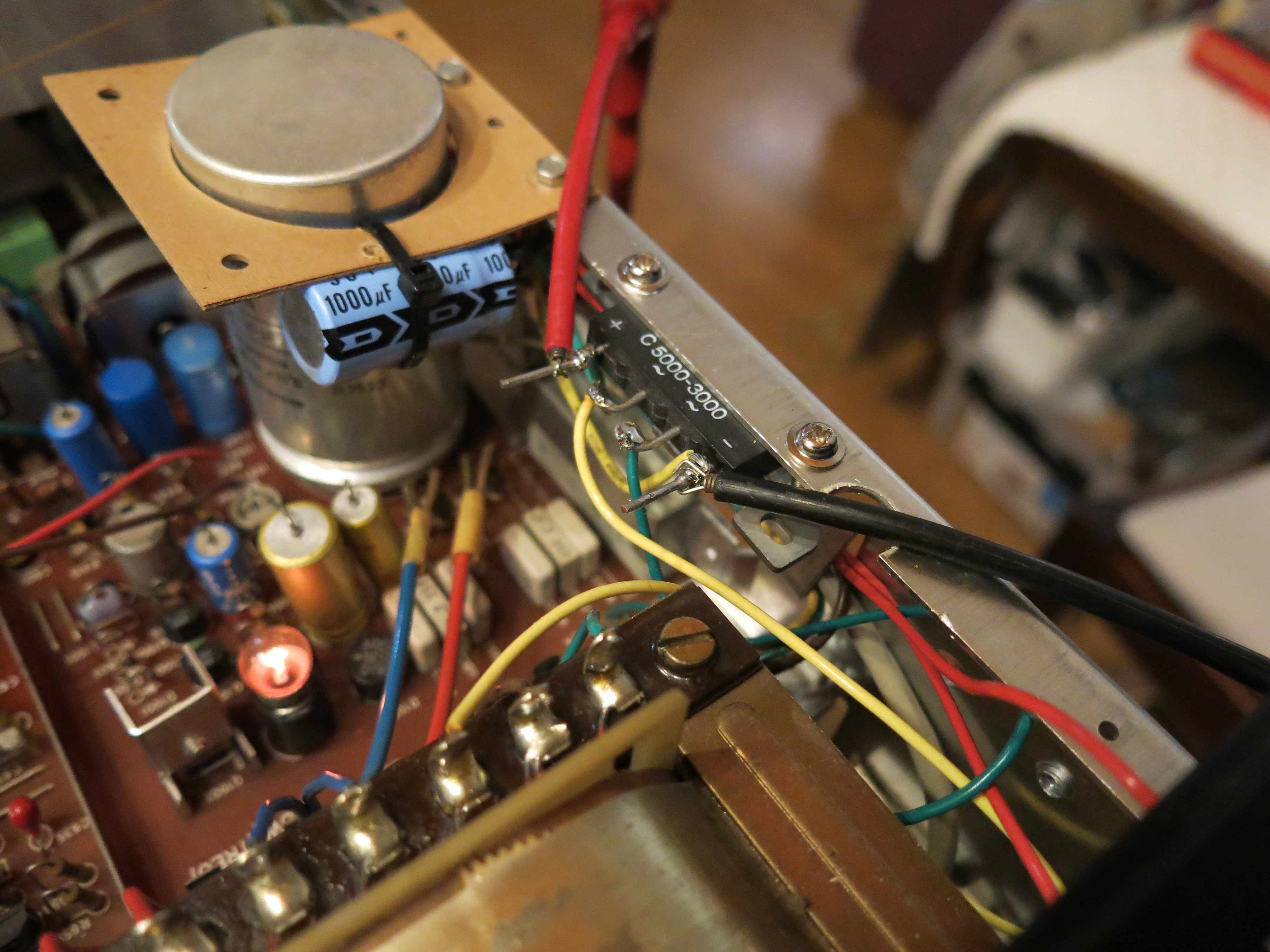
While LED functioned fine on AC current flickering where notisble. An 3 ampere rectifier where installed clamped to the top edge of the chassis, right over the main rectifier. With a 1000µF cap the new circuit now output 7.8V DC with no load. Note: Brown wire to center tap for 4.2VAC indicator bulbs are removed taking these bulbs out of circuit. Later they be feed with positive DC current with the Brown wire connected to negative terminal on this new PSU.
75Ω resistor where used for each pair of LED. Tests after installation now show we can add at least another 75Ω in series with the finished LED strip and still have the blue come trought even in bright daylaight. While bright blue looks really cool it soon gets tiresome — dimmed down is proper way to go one think.
220mA (1.8W) current draw from all these LEDs are much less what a single bulb used to consume where total load where around 2.5A (15.5W).
A LM350 voltage regulator where installed after the new rectifier before I understood more tests should have been performed beforehand. As it turn out voltage drop are considerable from idling at 7.8V DC. Without voltage regulation I can only get some 700mA/5VDC. This would need a LDO (low dropout regulator) rather than the LM350 regulator to be useful.
Loading the rectifier harder with a 2.2Ω resistor voltage now drops down to 4.09VDC ≈ 1.9A.
To keep these figures indicator bulbs also have to be converted to LED, or removed from circuit with it's total load of 575mA when all bulbs are on.
Not sure this will perform as planned with RPi B3+ needing close to 980mA at full throttle, — idling at some 350mA. Then add a dedicated DAC+ DSP hat from HiFiBerry system will work close to the edge with regards to keeping voltage within specification.
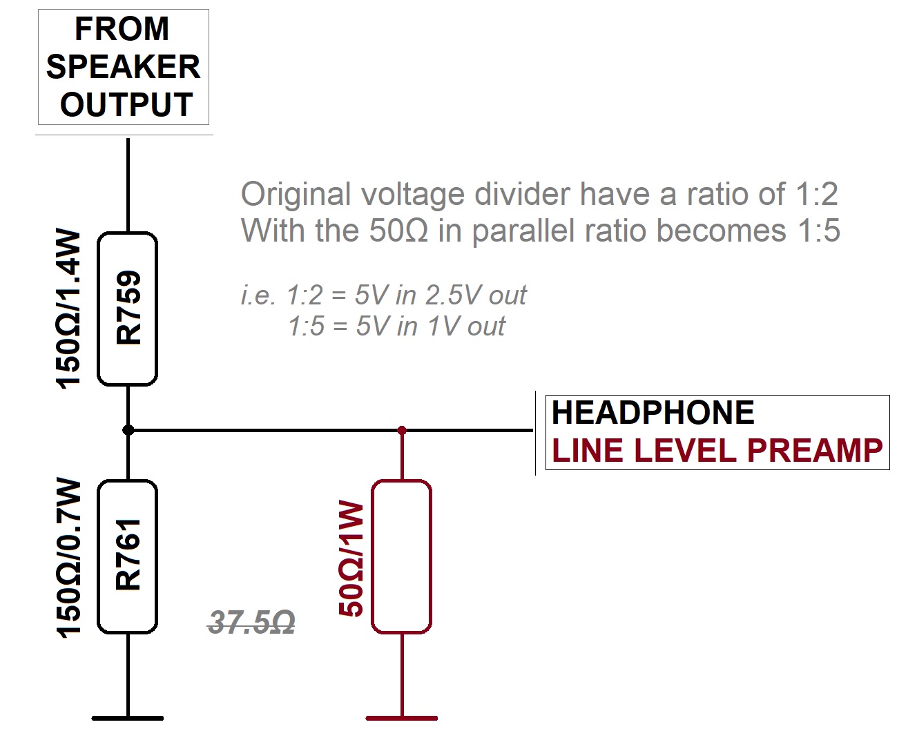
Not planning to use this Huldra 10 with any wintage tape machines bringing Line Out levels up closer to modern specification seems a good idea. Current configuration has 40k ohm output impedance and 8 times lower output gain than most modern gear. Higher output will prove very useful if H10 phono amplifier and RIAA are to be used as stand alone device.
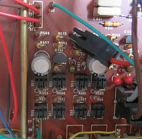
AUX Out — Remove R561, R562 (47kΩ, leave emty) and replace the two 330kΩ resistors R567, R568 with 10kΩ.
TAPE Out — Remove R565 and R566 (47kΩ, leave emty) and replace the two 330kΩ resistors R571, R572 with 10kΩ
PCB revision 41160-6 in this reciver resistors R567, R568, R571, R572 where 280kΩ
Kjell B used to recommend using some 10kΩ vintage carbon resistors in these positions. For period correct resistors 10kΩ values can be fount in the AM tuner at R319, R329, R335, R336 and a few others. They could be replaced with modern resistors, or just removed if AM tuner aren't in use. I chose to replace them. Not finding R319 instead snagged R313, part of a divider network I got a little jittery ending up with a burned transistor if removed.
One aberration for the line out mod could be to mount RCA sockets witht it's own 10kΩ resistor and leave the 330kΩ in place. Then mount a switch to the 47kΩ resistor going to ground (those we removed). This setup will then let us hook up and configure the DIN socket for vintage gear switching in the 47kΩ, and use RCA for modern without the 47kΩ to ground. With only one device physically connected at any time thought.
Schematics for TR-1000 actually show similar setup, but the 330kΩ resistor are 150kΩ with 47kkΩ always in circuit to ground with seperate 10kΩ resistors inline for the RCA sockets.
Utilizing KISS, just keep one output unmodified..
The initial idea where to find a way to shut down any oscillators when H10 where used for amplification only. Several hours were wasted to trace main PCB. Sadly revision 41160-6 PCB layout does not show up in any of the service manuals I found online.
Interesting I found the screening bar going over the PCB front to back do not all go to ground as expected. The one separating PSU and preamp actually feed 25V to one part of the AM tuner. The AM oscillator takes 25V from the switching system in front. So does the FM tuner.
As it turns out Tandberg had the same idea that turning off the radios completely is preferred. This can be seen by watching the small bulb inside the 25V power supply. The more current the system draw the more this bulb will light up. From barely glowing when any of the line level Phono/Tape/Aux are selected. To very visible when any of the AM band are active. And full glow when FM with presets are selected.