TCTp - The Clone Tone project
Peavey Rock Master tube guitar preamp clone project
This project never finished as general interest in the Rock Master took a hit when everyone
wanted a modeler amp I finally had the opportunity to own a real Rock Master preamp.
Now at this moment in time interest in the real tube pre-amp has grown again I desided
to post my old web page for others to maybe learn from.

"Why bother cloning the Rockmaster? You can have one dirt cheep from eBay!"
Well, that doesn't seems to be true any more. Many people that own one often make sure they got
two or three units these days. Past year I'm been offered only two units, and asking price was
equal to decent combos...
If you already own one you might want to improve part of it's design but hesitate to tweak your
perfectly working tone machine. Building one from scratch you can experiment with tone controls,
remote switches, MIDI control and more.
Idea for the project
The idea for this project is not to clone the complete preamp with bolts and nuts, but rather
try to nail the tone this beast is famous for. If possible we could break down the amp in smaller
modules that can be build on. For instance first start with the clean channel and leave out EFX
loops and maybe make them optional later on. Or separate the tone control so it can be duplicated
to other channels... - Maybe make it more simple and stuff it inside a stomp box?
Project start, collecting info for the project
Schematics
http://www.blueguitar.org/new/schem/peavey/rockmaster_91.jpg
Foot switch schematics
RM foot switch control schematics
Flow chart
Redrawn from usermanual
Only the clean channel. Maybe the first stage of the to be cloned?
User manual
http://www.peavey.com/support%5Csearchmanuals%5Clist%5Crockmasterpreamp.cfm
Sound clip
http://bongo666.free.fr/solo.theatre.essais6.rockmaster%20+%20strat%20+m300.mp3
http://bongo666.free.fr/03%20-%20journey.squelette5.EQ.+treble.%20medium%20+..reverb.vol%20+.mp3
http://bongo666.free.fr/essais%20jazz/giaz-01.mp3
Mods
A collection of mods for the Rock Master
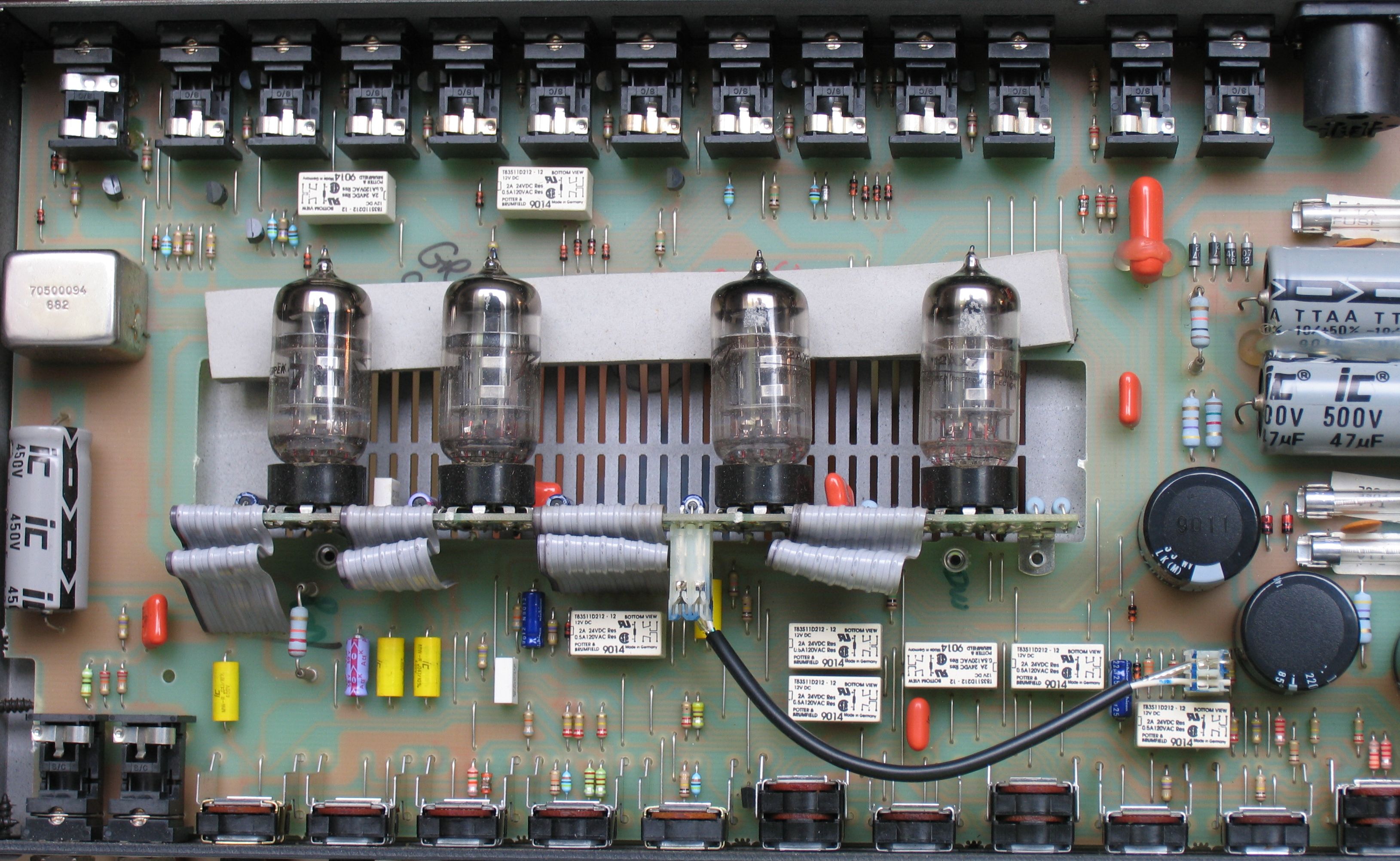
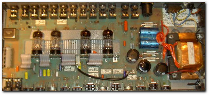
Peek inside
Parts list - incomplete
Breakaway Board - All components acountet for - total of 38 including tubes
V1, V2, V3, V4 - 4 pc 12AX7 tubes
C3 - 22uF 25V
C14 - .001uf
C16 - .22uF 400V
C17 - .47
C18 - 22uF 25V
C25 - 22uF 25V
C40 - .1uF 250V
C42 - 100pF
R3 - 150k
R4 - 1k5
R12 - 1M
R13 - 150k
R14 - 2k2
R16 - 220k
R17 - 470k
R20 - 100k
R21 - 1k5
R22 - 680k
R23 - 1M
R24 - 100k
R25 - 1k5
R32 - 100k
R37 - 1M
R38 - 2k2
R39 - 100K 1W
R41 - 1k5
R43 - 100k 1W
R55 - 470k
R103 - 1k5
R150 - 100k 1W
R308 - 100k
CR1 - 1N4148
CR2 - 1N4148
C400 - .1uF 400V
Main Board
R1 - 22k
R2 - 22k
R5 - 220k
R6 - 68k
R7 - 220k
R8 - 220k
R11 - 2k2 or 2M2
R27 - 10k
R105 - 470k
R600 - 10k
VR1 1M log - Clean Gain
VR2 250k log - Low EQ
VR3 50k lin - Mid EQ
VR4 250k lin - High EQ
VR5 10k lin - Presence
VR6* 50k log - Crunch Gain
VR7 50k lin - Crunch - Prost
VR8* 1M log - Ultra Gain
VR9 50k lin - Ultra Post
VR10 250k lin - Bottom
VR11* 250k lin - Body
VR12 250k lin - Edge input
(*) original with pull switch
C1 - 39pF
C2 - .1uF 250V
C4 - .047uF 400V
C5 - 820pF
C6 - 270pF
C7 - .1uF 10V
C8 - .047uF
C13 - .047uF 400V
C15 - .47uF 10V
C24 - .047uF 400V
C306 - .1uF 10V must be verified
C600 - .047uF
Other stuff
4 pc 9 pinn tube socket
Relay function
K1 K5 K7 controlled by foot switch Normal/Bypass
K2 K3 K8 controlled by foot switch Ultra/Crunch
K4 activated by both Ultra VR8 & Crunch VR6 trough K2B
K6 activated by Shift VR11
Look at the layout diagram
Tube layout and function
Posted by tmenzo on the Peavey Forum in thread "Rockmaster preamp tube layout..."
http://forums.peavey.com/default.asp?action=9&read=79918&fid=11#344620
Order is V1, V2, V3 and V4 from the input jack end.
The functions are:
V1A - input stage
V1B - pregain recovery stage
V2A,B - Ultra/Crunch circuits
V3A - active EQ for Ultra/Crunch
V3B - FX loop driver stage (cathode follower)
V4A - FX loop recovery
V4B - output stage (cathode follower)
V1 and V4 are always in use, while V2 and half of V3 are only used in the Ultra/Crunch channels.
PCB
Layout using the free ExpressPCB / ExpressSCH applications - http://www.expresspcb.com
You might want to use another pcb cad, but please share your design with us anyway :-)
Schematics and PCB layouts
Custom SchComponents used in this projct like 12AX7, relay
Parts details and data sheet
JJ Electronic ECC83S / 12AX7 tubes - http://www.jj-electronic.sk/pdf/ECC%2083%20S.pdf
9 pinn tube socket example with shield and one without shield from Banzai Musical Products
J174 P-Channel JFET Switch [Fairchild] used in the effect loop section
Local folder